


Page 6–10
2101510 Rev. AG
6)
Perform the
Feed-through Assembly Blockage Test
found in this chapter, on
the sample vent (SV). If the test fails, replace the feed-through assembly.
Otherwise, continue to next step.
7)
Check the sampling system for leaks and tubing restrictions. Repair the leak or
restriction, if found. Otherwise, continue to next step.
8)
Perform start-up diagnostics. If the stream test fails, continue to the next step.
9)
Follow
instructions in Maintenance, verify filters are clean
and free of obstructions. If needed, replace filters.
Totalflow recommends that a replacement analytical module
be installed at this point and additional steps be performed in
a clean, lint free atmosphere.
Because the customer does not have the required equipment
to determine which specific module needs replaced, the final
instructions are by process of elimination, beginning with the
most likely module.
The Totalflow repair department offers a range of services for
troubleshooting and repairing/replacing the non-functioning
parts. For more information regarding the repair service,
contact customer service:
USA: (800) 442-3097 or International: 1-918-338-4880
10)
Using the
instructions in Maintenance, replace the
analytical module assembly.
11)
Using the
instructions in Maintenance, replace the GC
module.
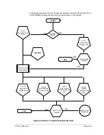
6.3.5
Oven Temperature Error Alarm
If the oven temperature error alarm is in system fault status, the following
procedure will step the user through the troubleshooting process. On occasion,
these instructions may detour the user to other procedures, and, when complete,
they should return to these procedures to continue.
6.3.5.1
Description
This alarm is indicative of an issue surrounding the ability to control the oven
temperature. The causes range from an unplugged cable, to an inability to
communicate with a sensor.
6.3.5.2
Instructions
1)
Verify that the auxiliary heater switch on the analytical processor board
coincides with the feed-through assembly configuration. If the feed-through
assembly has an installed auxiliary heater, verify that the switch on board
is set to normal. If no auxiliary heater is installed, the switch should be set
to override.
2)
Verify that the temperature sensor is plugged into the GC module.
3)
Follow the
procedure found in this chapter. If the test
fails, follow the Temperature Sensor to
instructions in
Maintenance. Otherwise, continue to the next step.
4)
The remaining options are not field-repairable. Using
instructions in, Maintenance, replace the analytical module assembly.


