


Page 3–18
2101510 Rev. AG
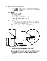
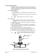
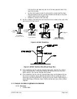
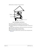
3.10 Pipe Saddle Installation
If installing an NGC using the pipe saddle mounting kit, use this procedure to
install the pipe saddle. Before beginning, review the procedure and the materials
required for installation. The optional pipe with flange may be used in installations
requiring additional stability.
3.10.1 Material Not Supplied
•
1 ea. pipe saddle
•
1 ea. 2” mounting pipe. Length dependent upon final overall NGC desired
height.
•
1 ea. 2” pipe with flange kit. (Optional kit comes with flange, screws, washers,
and coupling.)
Optional equipment may be ordered from Totalflow.
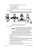
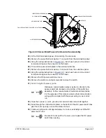
3.10.2 Instructions
1)
Position pipe saddle on meter run. Select a location that allows easy
access and is close to the sample probe. Lines should be a short as
possible.
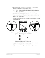
2)
Temporarily attach saddle on the meter run pipe using U-bolt and associated
hardware (see
3)
Screw one end of the 2” pipe into the saddle flange on the pipe saddle until
wrench tight. Place level against pipe and vertically align, adjusting saddle until
vertical alignment is achieved.
4)
After vertical alignment, securely tighten saddle mounting bolts.
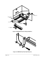
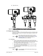
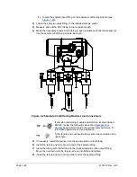
5)
If the configuration includes the optional pipe with flange, screw the 2” pipe
coupling onto the top of the mounting pipe using supplied hardware.
6)
Screw the optional mounting pipe with flange into the top of the pipe coupling.
Continue to the NGC Installation instructions. Method of
installation must be consistent with customer’s company
policy.
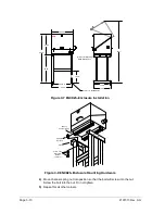
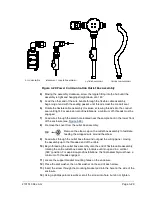
Figure 3-19 Typical Pipe Saddle Installation
METER RUN
"U" MOUNTING
BOLT
SADDLE
OPTIONAL MOUNTING
FLANGE PIPE
2" PIPE COUPLING


