


2101510 Rev. AG
Page 3–21
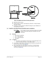
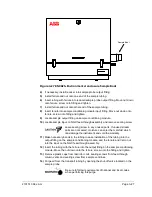
to the feed-through assembly and the termination panel located in the
rear of the housing.
•
For the shelf-mounted units, the unit would be oriented with the feed-
through assembly also facing forward. Sufficient clearance is required
when mounted near an inside corner.
•
Otherwise, continue to the next step.
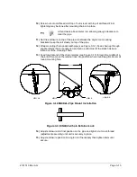
3)
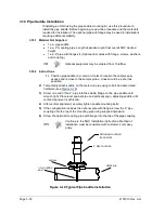
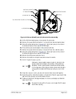
Secure in place by tightening the hex socket set screw, located in the neck of the
unit, using a 1/8” hex wrench.
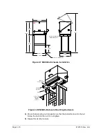
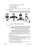
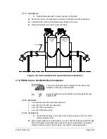
Figure 3-21 NGC Mounting
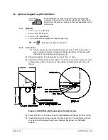
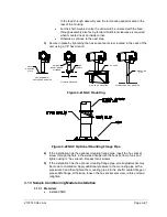
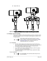
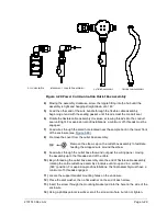
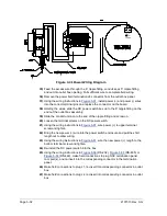
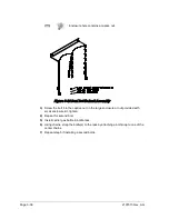
Figure 3-22 NGC Optional Mounting Flange Pipe
4)
If the installation has the optional mounting flange pipe, insert the hex socket
screw through the hole in the welded flange into the neck bottom of unit and
tighten using ¼” hex wrench. Repeat for all screws.
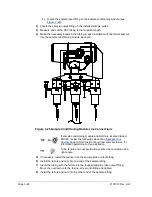
5)
If the installation has the optional mounting flange pipe, small adjustments may
be made to orientation. Apply additional pressure to the mounting pipe with a
pipe wrench and then tighten the mounting pipe into the shelf mounted flange or
pipe saddle flange. Otherwise, loosen the hex socket set screw, rotate unit and
retighten.
3.13 Sample Conditioning Module Installation
3.13.1 Materials
•
Installed NGC
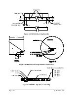
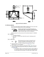
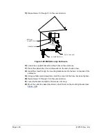
PIPE RUN MOUNTED
PIPE
SADDLE
WALL SHELF MOUNTING
WALL SHELF
STAND-ALONE PIPE MOUNTED
ENVIRONMENTAL
ENCLOSURE MOUNTED
2" MOUNTING
PIPE
ENC82
MOUNTING
PLATE
OPTIONAL
MOUNTING PIPE
W/FLANGE


