


Page 5–6
2101510 Rev. AG
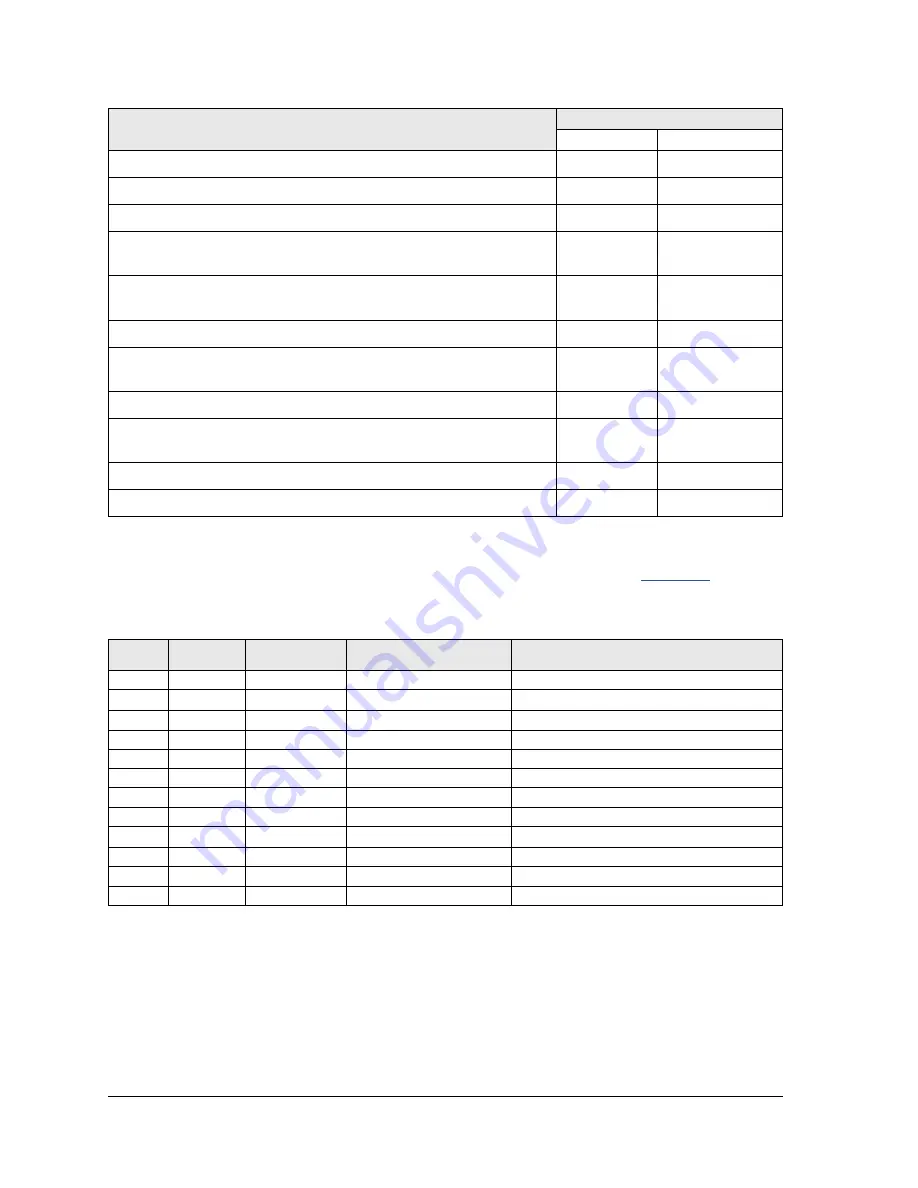
Part Description
Stock Application
1
>1
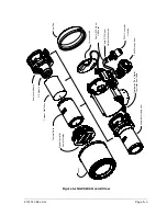
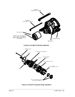
24 VDC Analytical Module assembly w/o GC Module
1
24 VDC Analytical Module assembly with GC Module
1
Cable between the Analog Processor and the Termination Board
1
1
Digital Controller Board and Display, Completed assembly.
1
1 per
application
Digital Controller Board Assembly (Auxiliary unit with no display)
1
1 per
application
Filter Frit for Feed-through Assembly
2
2
GC Module tested and characterized
1 per
application
MMI Port RS-232
1
1
Ribbon Cable for connection between the Digital Controller and
Termination Panel
1
1
Termination Panel
1
USB Local MMI Port
1
1
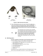
5.3 Field Tool Kit
The recommended NGC maintenance tools are presented in
included in the optional field tool kit.
Table 5–3 Tool Requirements
Qty
-001
-002
Part Number
Description
1
2102304-001
Bag, ABB Nylon 11” x 6” Tool
1
1800683-001
Cutter, 1/16” Tubing
1
1801690-001
Extractor Tool, IC 8-24 Pin
1
T10790
Hex Key, Set 1/16-5/16 (12 Pcs)
1
T10440
Screwdriver, 3/32 x 2” Standard
1
T10601
Stripper, Wire
1
1801821-001
Tool, Ball Driver, 10.3” Long, 5/16”
1
1801822-001
Tools, Nut Driver, 6” Shank, ¼”
1
1801820-001
Wrench, 10” Adjustable
1
T10805
Wrench, 3/8 x 7/16 Open End
1
T10800
Wrench, 1/4 x 5/16 Open End
1
1801819-001
Wrench, 6” Adjustable
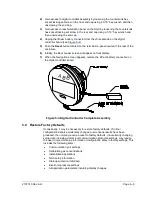
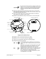
5.4 Visual Inspection
The NGC should be given an external visual examination on an established time
period. Visual checks maintain optimum system operation and accuracy of natural
gas sample analysis.
5.4.1
Inspection
During the visual inspection, components should be examined for the following
conditions:


