


Page 2–30
2101510 Rev. AG
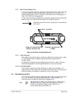
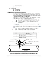
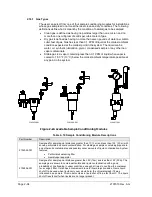
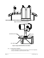
2.14.1 Location
•
Locate the pipeline coupling on the gas meter run in close proximity to the
NGC. This allows the stainless steel sample line from sample probe to
Chromatograph to be as short as possible.
•
The coupling should be mounted so the probe can be installed horizontally or
vertically on the meter run pipe. This means the coupling should be mounted
on either the top or the side of the meter run pipe.
•
Sample probe should not be mounted at the ends of headers, dead T’s, large
volume accumulators or other spots where gas is likely to be stagnant.
•
Installation should allow the probe to penetrate the center 1/3 of the main gas
meter run. This allows sufficient heat transfer with the flowing gas sample.
Sample probe inlet should be high enough to avoid sampling of liquids at the
bottom of the pipe.
•
The sample probe must be installed where the probe has access to the
fastest flow of gas within the pipe.
•
The sample probe should be mounted a minimum of five pipe diameters from
any device which could cause aerosols or significant pressure drops.
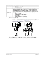
2.14.2 Other Considerations
•
TCR sample probe line pressure should be as close to 1-atmosphere as
possible to reduce sample transport lag times due to line pack. Sample
pressure at the NGC should be 15
±
2 psig (103
±
14 Kpa).
•
To maintain this pressure at the NGC filters, it may be necessary to increase
TCR sample probe pressure to a value greater than 15 psig. Pressure is
dependent on sample transport tubing length between the TCR sample probe
and analyzer.
•
Be sure to use tubing electrical isolators on sample tubing when connected to
pipelines that are not isolated from cathodic protection.
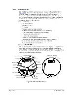
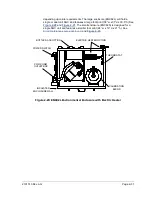
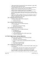
2.15 Environmental Enclosure (Optional Equipment)
In colder climates (ambient temperatures 0 °F to -40 °F) this environmental
enclosure (ENC82) allows mounting of the NGC directly on the pipe. This
insulated weatherproof enclosure has brackets for the NGC and a small start
up/calibration bottle. Having the calibration bottle in the heated enclosure ensures
a much more stable and consistent calibration.
2.15.1 Standard Features
•
Available with either an electric or catalytic heater option:
o
The catalytic heater is a 1500 Btu/hour input, and includes a standard
filter/drain kit.
o
The electric heater option features 120 VAC/400 W heater and
thermostat.
•
Sample conditioning system
•
Heated line entry
•
Rigid conduit
•
Mounts either as a free-standing unit or pipe mounted unit:
o
Large enclosure may be pipe-mounted on 4” through 12” pipe.
o
Small enclosure may be pipe-mounted on 2” through 5” pipe.
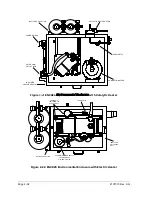
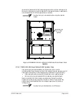
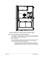
2.15.1.1
Enclosure
The heater and enclosure is designed to maintain a 40 °F inside temperature
when outside temperature is -40 °F. Two enclosures are available for installation


