


Page 3–72
2101510 Rev. AG
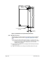
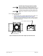
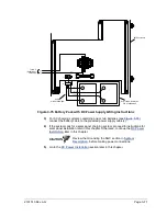
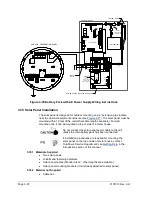
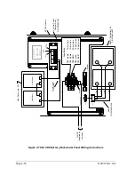
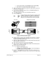
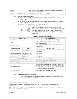
Figure 3-76 Battery Pack with AC Power Supply Wiring Instructions
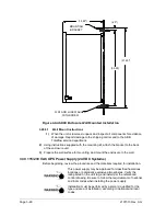
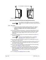
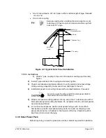
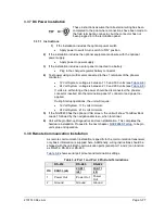
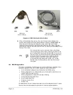
3.35 Solar Panel Installation
The solar panel is designed for outdoor mounting on a 2” extension pipe located
near the optional equipment enclosure (see
). The solar panel must be
mounted within 12 feet of the unit (other cable lengths available). For wall
mounted units, it can be mounted on top or side of a meter house.
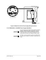
Do not connect the solar panel power cable to the unit
unless the main battery pack has been connected.
If installation procedures are required for mounting the
solar panel on the top or side of meter house, contact
Totalflow's Service Department; see
Introduction section of this manual.
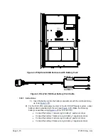
3.35.1 Materials Supplied
•
Two solar panels
•
U-Bolts and fastening hardware
•
Solar panel cables (Standard is 12’, other lengths are available.)
•
Solar panel mounting brackets (if not already attached to solar panel)
3.35.2 Material not Supplied
•
Cable ties
POWER SUPPLY
( ROTATED FOR CLARITY
)
ON OFF
SHLD GND
(+)
(-)
6770 ENCLOSURE
XFC/ XRC Bd.
BATTERY
(BT1)
( - ) ( + )
(+)
(-)
SECURITY
KEYPAD
J19
S1
J4
J23
J18
I/ O EXP
J15
MMI
J13
D
IS
P
L
A
Y
J10 J7
BATT
J16
(-)
(+)
C
O
M
M
2
C
O
M
M
1
1 2 3 4 5 6
8
7
9
1
0
XBT1
AUXPWR OUTPUT
DIGITAL I/O
J20
A
J8
CHARGER
INPUT
J6
J17
COMM2
B
COMM1
(-)
(+)
(+)
(-)
(+)
(-)
( SELECT EITHER
)
3- WAY
CONNECTOR
P/ N 2012907- 001
NGC 8201 TERMINATION PANEL
SERIAL PORT
1
SERIAL PORT
2
1
2
1
2
(+) (-) (+) (-) (+) (-) (+) (-)
INPUTS
OUTPUTS
(+)
(-)
J10
J8
DIGITAL I/O
POWER
S
2
RESET
S1
J7
J3
J2
J1
J5
J6
(-)
(+)
TERM
TERM
J11
J9
XMFR
(-)OUT
(-)OUT
(-)S
(+)S
(+)OUT
(+)OUT
AC
SWITCH
DC
FUSE
WARNING
DO NOT USE
SWITCH
UNLESS AREA IS
KNOWN TO BE
NON- HAZARDOUS
115/ 230V
AC IN
AC+
AC-
(+)
(-)
1A
2A
3A
4A
1B
2B
3B
4B
5B
6B
5A
6A
TB1
F1
A
B


