


2101510 Rev. AG
Page 3–77
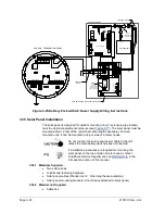
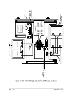
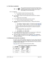
3.37 DC Power Installation
These instructions assume that all external wiring has been
completed to the point where connections have been made to
the field termination connector, but the connector has not
been plugged into the termination panel.
3.37.1 Instructions
1)
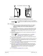
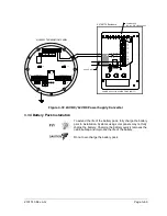
If the installation includes the optional power switch:
•
Apply power to switch; turn switch to “ON” position.
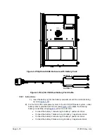
2)
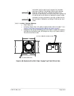
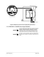
If the installation includes the optional equipment enclosure with the optional
power supply:
•
Apply power to power supply.
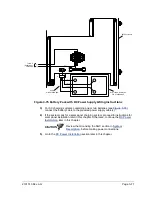
3)
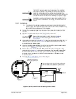
If the installation includes a solar panel connected to a battery:
•
Plug in the charger regulator battery connector.
4)
Test power using a multi-meter connected to the J1 terminals of the phoenix
connector:
•
12 Volt System: voltage is between 11.5 and 16.0 volts (see
•
24 Volt System: voltage is between 21.0 and 28.0 volts (see
If volts are within range, the power should be disconnected, the phoenix
connector inserted into the termination panel J1 connector and power re-
applied.
During Startup operations, the unit will require:
•
12 Volt System: 11.5 volts minimum.
•
24 Volt System: 21.0 volts minimum.
5)
If the NGC8200 has the optional VGA screen, the unit will show “Totalflow Boot
Loader” followed by the navigational screen, when functional.
6)
Unit will begin
Start-up Diagnostics
and oven stabilization. This completes the
hardware installation. Proceed to the next chapter,
, to begin
unit setup and operation.
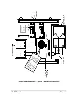
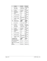
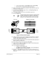
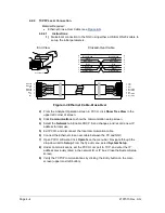
3.38 Remote Communication Installation
As remote communication installation is specific to the communication transceiver,
only basic information is supplied here. Additionally, wiring instructions should be
shipped with the unit. Both communication ports (serial port 1 and 2) can function
as RS-232, RS-422 or RS-485.
shows serial port pinouts and termination settings.
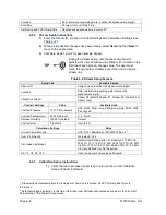
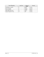
Table 3–2 Port 1 and Port 2 Pin-Outs/Terminations
RS-232
RS-485
RS-422
PIN
PORT 1 (J8)
PORT 1
(J8)
PORT 1
(J8)
1
Power Out
Power Out
Power
Out
2
Ground
Ground
Ground


