


2101510 Rev. AG
Page 6–33
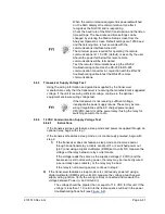
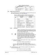
6.6.6.1
Instructions
Voltage on the following steps may be hard to see using a
digital multimeter. If available, an oscilloscope will provide a
more accurate reading. To verify, the host software must be
continuously polling the NGC.
Generally speaking, these tests performed on the terminal
board will only verify incorrect or damaged wiring. If all
previous testing passed and all wiring, jack and terminations
have been verified as correct, the board will need to be
replaced. Contact Totalflow customer service. See Getting
Help in the introduction of this manual for instructions.
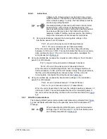
1)
Using an oscilloscope, measure the receiving data voltage on the
termination panel J8 or J10 between:
Port 1, J8–pin 2 (Ground) and pin 8 (Receive Data) or
Port 2, J10–pin 2 (Ground) and pin 8 (Receive Data).
When the unit is receiving data from the host, the voltage should vary
between -5 VDC and +5 VDC. This would indicate that the unit is receiving
data; continue to step 2. If the unit is not receiving data, investigate the
wiring issues (see
2)
Using an oscilloscope, measure the request to send voltage on the termination
panel J8 or J10 between:
Port 1, J8–pin 2 (Ground) and pin 6 (Request to Send) or
Port 2, J10–pin 2 (Ground) and pin 6 (Request to Send).
When the unit is communicating with the host, the voltage should be +5
VDC and 5 VDC until the XFC transmit stops. This would indicate
that the unit is transmitting data; continue to step 3. If the unit is not
receiving data, investigate the wiring issues (see
3)
Using an oscilloscope, measure the transmit data voltage on the termination
panel J8 or J10 between:
Port 1, J8–pin 2 (Ground) and pin 7 (Transmit Data) or
Port 2, J10–pin 2 (Ground) and pin 7 (Transmit Data).
When the unit is transmitting to the host, the voltage should vary between -5
VDC and +5 VDC. This would indicate that the unit is transmitting data. If
the unit is still not responding, continue to the next test as directed in
6.6.7
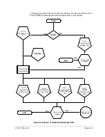
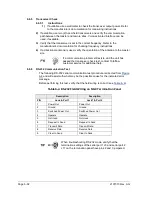
RS-485 Communications
The following RS-485 serial communication test procedure is directed from
and will assist with what may be the possible cause for the indicated error
message.
When troubleshooting RS-485 mode, verify the termination
settings of port 1 J9 and port 2 J11 on the termination panel
are correctly jumpered (see


