2101510 Rev. AG
Page 6–5
3)
Using the
Assembly instructions in
replace the analytical module assembly.
Totalflow recommends that a replacement analytical module
be installed at this point, and additional steps be performed
in a clean, lint free atmosphere.
The Totalflow repair department offers a range of services
for troubleshooting and repairing/replacing the non-
functioning parts. For more information regarding the repair
service, contact customer service:
USA: (800) 442-3097 or International: 1-918-338-4880
6.2.4
Processor Control Test
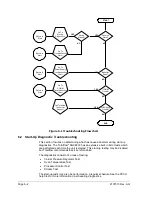
If Col 1 or Col 2 carrier pressure test failed, or the oven temperature test failed,
the following procedure will step the user through the troubleshooting process. On
occasion, these instructions may detour to other procedures, and when complete,
the user should return to these procedures to continue.
6.2.4.1
Description
These alarms are indicative of a lack of ability to control a function. If the failure is
either one or both of the column carrier pressure tests, it could be a missing or
failed gasket. If the failure is in the oven control temperature test, it could be
something as easy as a missing GC module cover or analytical module thermal
flask.
6.2.4.2
Instructions
1)
If the start-up diagnostics are being performed following the
disassembly/replacement of a module or spare part, insure that the unit is
completely reassembled, including the thermal flask and both the front and
rear end caps, and then re-start the diagnostics. If diagnostics again fail,
repeat disassembly steps and verify that all gaskets and connections are
tight and correctly installed. Otherwise, continue to the next step.
2)
If the start-up diagnostics are being performed from an initial startup, verify that
the analytical module is not loose inside the enclosure.
3)
Verify that the GC module is tight and that the cables are correctly installed and
not damaged.
4)
Reassemble the unit and restart diagnostics. If the unit continues to fail, replace
the entire analytical module and return to Totalflow for warranty
repair/replacement.
6.2.5
Stream Test
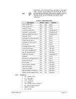
The stream flow diagnostics go through a series of tests, testing the stream
pressure at different conditions as listed below. Each column will display the
pressure results after that part of the test has completed. The status column will
reflect the current and final status of the tests.
The following procedure will step the user through the troubleshooting process.
On occasion, these instructions may detour the user to other procedures, and,
when complete, they should return to these procedures to continue.
During the stream test, streams with no gas pressure will fail
and will be disabled in the stream sequence. To enable
these streams, please click
Stream Setup
on the Analyzer
Operation screen.


