2101510 Rev. AG
Page 5–25
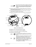
Figure 5-11 Primary Component Side Digital Controller Board
5.19 Replacing Frit Filters
Several reasons exist for replacing the frit filters from a scheduled maintenance
procedure to decrease sample pressure due to clogged filters. When replacing the
filters on a regularly scheduled maintenance plan, it will most likely not require that
the sample lines be removed from the external plate. When replacing the filters as
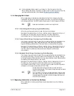
a troubleshooting measure, remove the sample input lines and use compressed
air to clear the pathway. For the purposes of this manual, these instructions
contain steps for the worst case scenario.
5.19.1 Instructions
1)
On the Analyzer Operation
screen, click
Hold
under Next Mode. When the
unit completes the current cycle and enters hold, continue to the next step.
2)
Collect data from the unit.
3)
Back up the configuration files, following the instructions detailed previously in
the section,
Backing Up Configuration Files (Save)
4)
Turn off all the sample streams, calibration gas and carrier gas.
5)
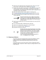
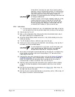
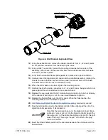
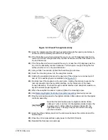
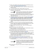
Using a 7/32” hex wrench, loosen and remove all 8–¼” hex socket screws (see
6)
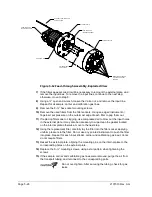
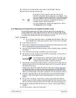
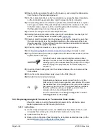
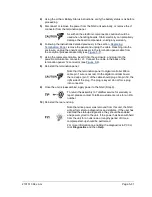
If space permits, lift the external plate away from the internal plate and view the
frit filters. If space does not permit lifting the plate away enough to view the filters,
remove the sample input lines and the carrier and calibration gas lines.
3
J6
1
2
14
2
1
J1
50
49
U14
U3
J2
U11
U19
U18
U20
U21
13
U10
1
J5
1
4
J7
SECURE DIGITAL CARD DRIVE
JTAG INTERFACE
14 PIN HEADER
3 PIN HEADER
LITHIUM BATTER
TERMINATION INTERFACE
50 PIN CONNECTOR
BOOT MODE
NOT USER
CONFIGURABLE
LCD INTERFACE
40 PIN CONNECTOR
CPU

