Start-up 57
The start sequence for the parameter example above is given
below.
Control word:
•
Reset the fieldbus communication fault (if active).
•
Enter 47Eh (1150 decimal)
→
READY TO SWITCH ON.
•
Enter 47Fh (1151 decimal)
→
OPERATING (Speed mode).
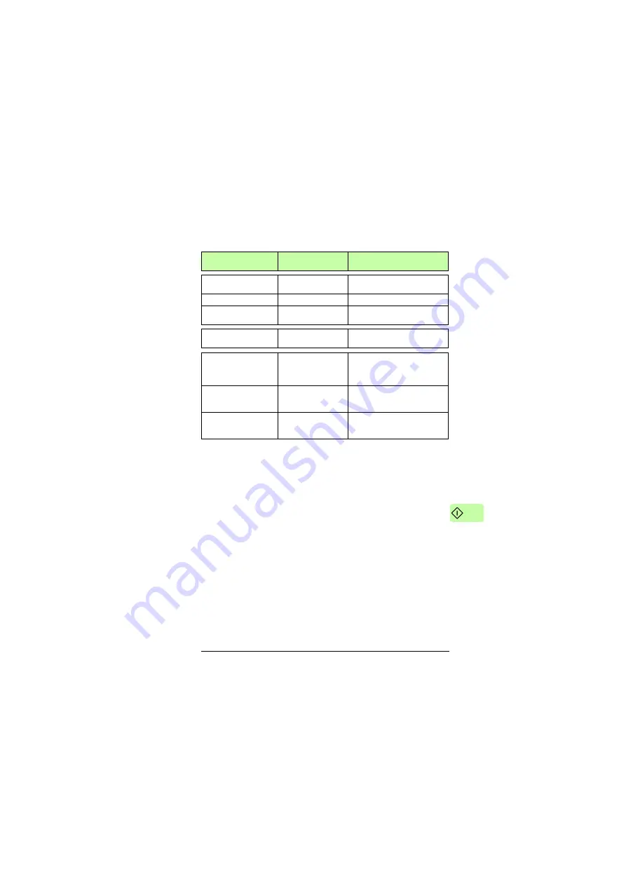
51.01 FBA type
136
= ETH Pwrlink
1)
Displays the type of the fieldbus
adapter module.
51.02 Profile
1
= ABB Drives profile
Selects the ABB Drives profile.
51.03 Node ID
3
2)
Defines the address of the
device.
51.27 FBA par refresh
1
= Configure
Validates the FEPL configuration
parameter settings.
20.01 Ext1 commands
12
= Fieldbus A
Selects the fieldbus A interface
as the source of the start and
stop commands for external
control location 1.
20.02 Ext1 start trigger
1
= Level
2)
Defines the start signal for
external control location 1 as
level-triggered.
22.11 Speed ref1
selection
4
= FB A ref1
Selects the fieldbus A reference 1
as the source for speed
reference 1.
1) Read-only or automatically detected/set
2) Example
Drive parameter
Setting for ACS880
drives
Description
Summary of Contents for FEPL-02 Ethernet POWERLINK
Page 4: ......
Page 10: ...10 Table of contents ...
Page 20: ...20 About the manual ...
Page 28: ...28 Mechanical installation ...
Page 63: ...Start up 63 2 To add the adapter module right click the IF3 list entry and then click Insert ...
Page 69: ...Start up 69 3 In the Project transfer dialog box click OK 4 Wait for the transfer to finish ...
Page 70: ...70 Start up When the transfer is finished the PLC starts up in the RUN mode ...
Page 90: ...90 Communication profiles ...
Page 100: ...100 Communication protocol ...
Page 104: ...104 Diagnostics ...
Page 108: ...108 Technical data ...


