6
-158
Using PG Speed Control Board
There are four types of PG Speed Control Board that can be used in V/f control with PG.
•
PG-A2: A-phase (single) pulse input, compatible with open collector or complimentary outputs.
•
PG-B2: A/B-phase pulse input, compatible with complimentary outputs.
•
PG-D2: A-phase (single) pulse input, compatible with line drivers.
•
PG-X2: A/B/Z-phase pulse input, compatible with line drivers.
There are two types of PG Speed Control Boards that can be used for flux vector control.
•
PG-B2: A/B phase pulse inputs, complementary outputs
•
PG-X2: A/B/Z phase pulse inputs, line driver outputs
For the connection diagram, refer to page 2-36 to 2-38.
Setting Number of PG Pulses
Set the number of PG (Pulse Generator/Encoder) pulses in pulses/rotation. Set the number of A-phase or B-
phase pulses per 1 motor rotation in F1-01.
Matching PG Rotation Direction and Motor Rotation Direction
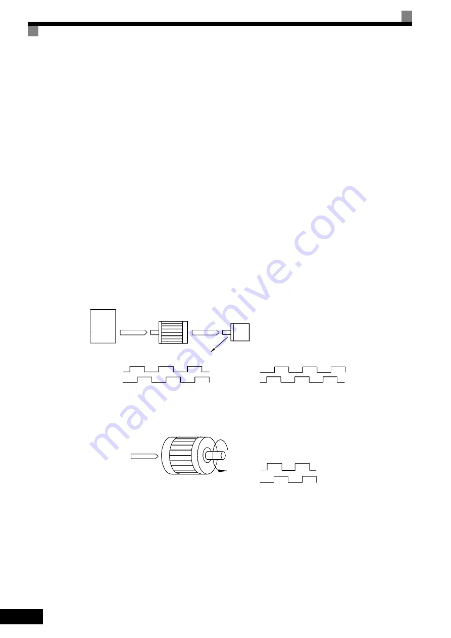
Constant F1-05 matches the PG rotation direction and the motor rotation direction. If the motor is rotating for-
wards, set whether it is A-phase driven or B-phase driven. Make this setting when using PG-B2 or PG-X2.
Fig 6.78 PG Rotation Direction Setting
Generally, PG is A-phase driven when rotation is clockwise (CW) see from the input axis. Also, motor rota-
tion is counter-clockwise (CCW) seen from the output side when Forward Commands are output. Conse-
quently, when motor rotation is forward, PG is normally A-phase driven when a load is applied, and B-phase
driven when a load is not applied.
Inverter
Forward
Command
Motor
PG (encoder)
Pulse output
A-phase driven when set value = 0
B-phase driven when set value = 1
A-phase
A-phase
B-phase
B-phase
Example: Forward rotation of standard Yaskawa motor (PG used: Samtack (KK))
Forward
Command
Motor output axis rotates
counter-clockwise during In-
verter Forward Command.
Rotation
(CCW)
A-phase
B-phase
Yaskawa standard PG used is A-phase driven (CCW) when motor rotation is forward.


