6
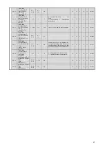
Table 4.2.2 Parameter Table (1)
Differences with Yaskawa's standard drives are marked with gray shading.
Parameter Access Level
Note-2
Function
No.
Parameter Name
(Digital Operator
Display)
Setting
Range
Setting
Units
Factory
Settings
Comments
Chan
ges
on
the
Fly
V/f
V/f
w/P
G
OLV CLV
Memo
bus
Address
A1-00
Language Selection
(Select Language)
0,2~5
1
0,2~5
Note-1
0: English
2: German
3: French
4: Italian (some messages in English)
5: Spanish
Y
A
A
A
A
100H
A1-01
Access Level
(Access Level)
0~2
1
2
Selects which parameters are
accessible via the Digital Operator.
0: Operation Only
1: User Level (only available if A2
parameters have been set)
2: Advanced Level
Y
A
A
A
A
101H
A1-02
Control Method
Selection
(Control Method)
0~3
1
2
Note-1
Selects the Control Method of the
Drive.
0: V/f control without PG
1: V/f control with PG
2: Open Loop Vector
3: Flux Vector (Closed Loop Vector)
N
Q
Q
Q
Q
102H
A1-03
Initialize Parameters
(Init Parameters)
0000~
2220
1
0000
1110: User Initialize (The user must
first set their own parameter values
and then store them using parameter
o2-03.)
2220: 2-Wire Initialization
N
A
A
A
A
103H
A1-04
Password 1
(Enter Password)
0000~
9999
1
0000
N
A
A
A
A
104H
Initializat
ion
A1-05
Password 2
(Select Password)
0000~
9999
1
0000
N
A
A
A
A
105H
User
Param.
A2-01
|
A2-32
User Parameter 1
(thru 32)
(User Parameter 1 to
32)
-
-
-
N
A
A
A
A
106H
~125H
b1-01
Reference Selection
(Reference Source)
0~4
1
1
0: Digital Operator
1: Control Circuit Terminal
2: Memobus Communication
3: Option Card
4: P ulse Input
N
Q
Q
Q
Q
180H
b1-02
Operation Method
Selection
(Run Source)
0~3
1
1
0: Digital Operator
1: Control Circuit Terminal
2: Memobus Communication
3: Option Card
N
Q
Q
Q
Q
181H
b1-03
Stop Method Selection
(Stopping Method)
0~3
1
0
0: Ramp to St op
1: Coast to Stop
2: DC Injection to Stop
3:Coast with Timer (A new run
command is ignored if received
before the timer expires).
N
Q
Q
Q
Q
182H
b1-04
Reverse Operation
Selection
(Reverse Oper)
0~2
1
0
0: Reverse Enabled
1: Reverse Disabled
2: Exchange Phase - Change direction
of forward motor rotation.
N
A
A
A
A
183H
b1-05
Operation Selection
for Setting of E1-09 or
less
(Zero-speed Oper)
0~3
1
0
Operation method when frequency
reference is less than minimum output
frequency set in E1-09.
0: Operates according to frequency
reference (E1-09 is disabled)
1: Output shuts off (coast to stop if less
than E1-09)
2: Operates according to E1-09
(frequency reference set to E1-09)
3: Zero speed (frequency reference of
zero is less than E1-09)
N
N
N
N
A
184H
Mode of Operation
b1-06
Read Sequence Input
Twice
(Cntl Input Scans)
0,1
1
1
0: 2ms - 2 scans (for quick response)
1: 5ms - 2 scans (for noisy
environments)
N
A
A
A
A
185H
b2-01
Zero Speed Level (DC
Injection Braking
Staring Frequency)
(DC Inj Start Freq)
0.0~
10.0
0.1
Hz
0.5
N
A
A
A
A
189H
b2-02
DC Injection Braking
Current
(DC Inj Current)
0~100
1%
50
Sets the DC injection braking current
as a percentage of the Drive rated
current.
N
A
A
A
N
18AH
b2-03
DC Injection Braking
Time at Start
(DC Inj Time @Start)
0.00~
10.00
0.01
sec
0.00
N
A
A
A
A
18BH
DC Injection Braking
Time at Stop
(DC Inj Time @Stop)
DC Injection Braking
b2-04
Stop Timer
(Stop Timer)
0.00~
10.00
0.01
sec
0.00
*
**
**Factory/default settings will vary
based on Control Mode (refer to
attached table).
**The lower frame will be displayed
when in Flux Vector Mode.
N
A
A
A
A
18CH
Содержание CIMR-F7Z
Страница 3: ......


