


12
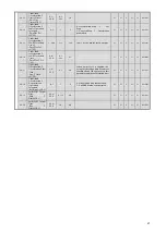
Table 4.2.2 Parameter Table (6)
Parameter Access Level
Note-2
Function
No.
Parameter Name
(Digital Operator
Display)
Setting
Range
Setting
Units
Factory
Settings
Comments
Chan
ges
on
the
Fly
V/f
V/f
w/P
G
OLV CLV
Memo
bus
Address
F1-06
PG Division Rate
(PG Pulse
Monitor)
(PG Output Ratio)
1~132
1
1
Enabled only with PG-B2 Control
Board.
N
N
A
A
A
385H
F1-07
Integral Value
During
Accel/Decel
Enable/Disable
(PG Ramp PI/I
Sel)
0,1
1
0
0: integral Operation Disabled
1: integral Operation Enabled
N
N
A
N
N
386H
F1-08
Overspeed
Detection Level
(PG Overspd
Level)
0~120
1%
115
N
N
A
N
A
387H
F1-09
Overspeed
Detection Delay
T ime
(PG Overspd
Time)
0.0~
2.0
0.1
sec
0.0
*
*Factory/default settings will vary
based on Control Mode (refer to
attached table).
N
N
A
N
A
388H
F1-10
Excessive Speed
Deviation
Detection Level
(PG Deviate
Level)
0~50
1%
10
N
N
A
N
A
389H
F1-11
Excessive Speed
Deviation
Detection Time
(PG Deviate Time)
0.0~
10.0
0.1
sec
0.5
N
N
A
N
A
38AH
F1-12
Number of PG
Gear Teeth 1
(PG # Gear Teeth
1)
0~
1000
1
0
N
N
A
N
N
38BH
F1-13
Number of PG
Gear Teeth 2
(PG # Gear Teeth
2)
0~
1000
1
0
N
N
A
N
N
38CH
PG Option Setup
F1-14
PG Open-Circuit
Detection Time
(PGO Detection
Time)
0.0~
10.0
0.1
sec
2.0
N
N
A
N
A
38DH
AI
-14 Setup
F2-01
Bi-polar or
Uni-polar Input
Selection
(AI-14 Input Sel)
0,1
1
0
0: 3CH Separate Input
1: 3CH Addition Input
N
A
A
A
A
38FH
DI
-14 Setup
F3-01
Digital Input
Option
(DI Input)
0~7
1
0
0: BCD 1% 4: BCD 0.1Hz
1: BCD 0.1% 5: BCD 0.01Hz
2: BCD 0.01%
6: BCD
(5-digit) 0.01Hz
3: BCD 1Hz 7: Parity
(displays 10 digits of setting value )
N
A
A
A
A
390H
Содержание CIMR-F7Z
Страница 3: ......


