13
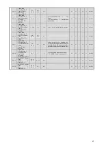
Table 4.2.2 Parameter Table (7)
Parameter Access Level
Note-2
Function
No.
Parameter Name
(Digital Operator
Display)
Setting
Range
Setting
Units
Factory
Settings
Comments
Chan
ges
on
the
Fly
V/f
V/f
w/P
G
OLV CLV
Memo
bus
Address
F6-01
Operation
Selection after
Commun ication
Error
(BUS Fault Sel)
0~3
1
1
0: Deceleration Stop 2: Fast Stop
1: Coast to Stop
3: Alarm Only
N
A
A
A
A
3A2H
F6-02
Input Level of
External Fault
from
Communications
Option Card
(EF0 Detection)
0,1
1
0
0: Always detected.
1: Fault detection only
while
operating.
N
A
A
A
A
3A3H
F6-03
Stopping Method
for External Fault
from
Communications
Option Card
(EF0 Fault Action)
0~3
1
1
0: Deceleration Stop 2: Fast Stop
1: Coast to Stop
3: Alarm Only
N
A
A
A
A
3A4H
F6-04
Trace Sampling
from
Communications
Option Card
(Trace Sample
Tim)
0~
60000
1
0
N
A
A
A
A
3A5H
F6-05
Current monitor
unit selection
(CurrentUnitSel)
0~1
1
0
0: Ampere
1: 100% / 8192
N
A
A
A
A
3A6H
Communication Options
F6-06
Torque
Reference/Torque
Limit Selection
from Optical
Option
(Torq Ref/Lmt sel)
0,1
1
0
0: Torque ref/limit from option board
disabled
1: Torque ref/limit from option board
enabled.
N
N
N
N
A
3A7H
H1-01
Terminal S3
Function Selection
(Terminal S3 Sel)
1
24
N
A
A
A
A
400H
H1-02
Terminal S4
Function Selection
(Terminal S4 Sel)
1
14
N
A
A
A
A
401H
H1-03
Terminal S5
Function Selection
(Terminal S5 Sel)
1
0
N
A
A
A
A
402H
H1-04
Terminal S6
Function Selection
(Terminal S6 Sel)
1
3
N
A
A
A
A
403H
Multi
-Function Inputs
H1-05
Terminal S7
Function Selection
(Terminal S7 Sel)
**
00~78
1
9
**Possible settings will vary based on
Control Mode (refer to attached
table).
N
A
A
A
A
404H
H2-01
Terminal M1-M2
Function
Selection(Contact)
(Term M1-M2 Sel)
1
21
N
A
A
A
A
40BH
H2-02
Terminal P1
Function Selection
(Term P1 Sel)
1
1
N
A
A
A
A
40CH
Multi
-Function Digital
Outputs
H2-03
Terminal P2
Function Selection
(Open Collector)
(Term P2 Sel)
**
00~37
1
2
**Possible settings will vary based on
Control Mode (refer to attached
table).
N
A
A
A
A
40DH
H3-01
Signal Level
Selection
(Terminal A1)
(Term A1 Signal)
0,1
1
0
0: 0 to +10VDC
1: -10V to +10VDC
N
A
A
A
A
410H
H3-02
Gain (Terminal
A1)
(Terminal A1
Gain)
0.0~
1000.0
0.1%
100.0
Y
A
A
A
A
411H
H3-03
Bias (Terminal
A1)
(Term A3 Bias)
-100.0
~
100.0
0.1%
0.0
Y
A
A
A
A
412H
H3-08
Multi-Function
Analog Input
Terminal A2
Signal Level
selection
(Term A2 Signal)
0~2
1
2
0: 0 to +10V input 2: 4~20 mA
1: -10 V to +10V input
N
A
A
A
A
417H
Analog Inputs
H3-09
Multi-Function
Analog Input
Terminal A2
Function Selection
(Terminal A2 Sel)
**
0~1F
1
0
**Setting Range will vary based on
Control Mode (refer to attached
table).
N
A
A
A
A
418H
Содержание CIMR-F7Z
Страница 3: ......


