


28
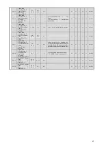
U3-18
Elapsed Time of 8th
Fault
(Elapsed TIme 8)
1H
-
A
A
A
A
811H
U3-19
Elapsed Time of 9th
Fault
(Elapsed TIme 9)
1H
-
A
A
A
A
812H
U3-20
Elapsed Time of 10th
Fault
(Elapsed TIme 10)
1H
-
A
A
A
A
813H
4.2.3 Multi-Function Input Terminal Functions
Any changes made from the standard inverter are indicated by bold outline and gray shading.
Setting
Value
Multi-Function Input Terminal Functions
(H1-01, -02, -03, -04, -05)
Multi-Function Output Terminal
Functions
(H2-01, -02, -03, -04, -05)
Multi-Function Analog Input Terminal Functions
(H3-09)
00
Brake Release Check
During Run
Terminal A1 and Calculations
01
-
Zero Speed
Frequency Gain
02
Option/Inverter Selection
Frequency (Speed) Agree 1)
Second Speed Analog (Auxiliary Frequency
Command 1)
03
Multi-Step Speed Command 1
Random Frequency (Speed) Agree 1
04
Multi-Step Speed Command 2
Frequency (Fout) Detection 1 >
Output Voltage Bias
05
Multi-Step Speed Command 3
Frequency (Fout) Detection 1 <
Accel/Decel Time Gain (Compression
Co-Efficient)
06
Jog (JOG) Frequency Selection
Inverter Operation Preparations
Complete
DC Braking (DB) Current
07
Accel/Decel Time Selection 1
Main Circuit Undervoltage (UV) During
Detection
Overtorque/Undertorque Detection Level
08
Baseblock Command N.O. (N.O. Input)
During Baseblock
Stall Prevention Level During Run
09
Baseblock Command N.O. (N.C. Input)
Frequency Command Select ion Status
-
0A
Hold Accel/Decel Stop
Operation Command Status
Jump Frequency
0B
Inverter Overheat Warning (OH2)
Overtorque/UndertorqueDuring
Detection 1 N.O. (N.O. Output)
-
0C
Multi-Function Analog Input Selection
(Enabled/Disabled)
During Frequency Command Loss
Overload Detection Level
0D
V/f w/PG, without Speed Control
Pre-Installed Braking Resistance
Malfunction
Frequency Bias 2
0E
Speed Control integral Reset
Fault
Motor Temperature Input
0F
Not Used
Not Used
-
10
UP Command
Minor Error
Positive Side Torque Limit
11
DOWN Command
Fault Reset
Negative Side Torque Limit
12
FJOG Command
-
Regen Domain Torque Limit
13
RJOG Command
Frequency (Speed) Agree 2
-
14
Fault Reset
Random Frequency (Speed) Agree 2
Torque Compensation
15
Emergency Stop (N.O. Relay Input)
Frequency (Fout) Detection 2 >
P/N, Torque Limit on both sides
16
Motor Switch Command
Frequency (Fout) Detection 2 <
17
Emergency Stop (N.C. Input)
Overtorque/UndertorqueDuring
Detection 1 N.C. (N.C. Output)
18
Overtorque/UndertorqueDuring
Detection 2 N.O. (N.O. Output)
19
-
Overtorque/UndertorqueDuring
Detection 2 N.C. (N.C. Output )
1A
Accel/Decel Time Selection 2
While in Reverse
1B
Permission to Write to Parameters
During Baseblock 2
1C
+ Speed Command
Motor Selection (when 2
nd
motor is
selected)
1D
- Speed Command
Regen During Run
1E
Analog Frequency Command
Sample/Hold
-
-
1F
Motor Overload OL1 (incl. OH3) Alarm
Warning
H3-09: Analog Input is not used.
20
Inverter Overheat Warning OH Alarm
Warning
21
Brake Release Command
22
External Fault
Overload Detection (N.O. Output )
23
Overload Detection (N.C. Output )
24-2F
-
30
Swift Lift 1 Enabled/Disabled
REV-1
During Torque Limit (Current Limit)
31
Travel Limit Input (Forward, N.O. Input )
REV-1
-
32
Travel Limit Input (Forward, N.C. Input)
REV-1
Speed Limit Circuit During Run (for
Torque Control)
33
Travel Limit Input (Reverse, N.O. Input)
REV-1
Zero Servo Complete
34
Travel Limit Input (Reverse, N.C. Input)
REV-1
-
35
Collision Stop Enabled/Disabled
REV-1
-
36
Swift Lift 2 Enabled/Disabled
REV-1
-
37
Multi-Step Speed Command 4
During Run 2
38-5F
-
60
DC Braking Command
61-66
-
67
Communication Test Mode
68~71
-
-
Содержание CIMR-F7Z
Страница 3: ......