35
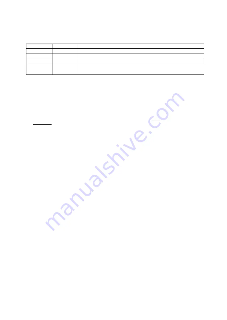
(1) Terminal S1 and S2 (Forward Run Command, Reverse Run Command)
The operations shown below are executed when the steady signal is entered based on the combination of the forward
and reverse run commands.
Operations may be restricted in some way based on the Run Command Tuning Function. For mo re information, see
the description listed in section 6.2, “Run Command Tuning Function”
FWD Command
REV Command
Operations
Open
Open
Decelerates to stop as shown in 6.1.2, “ Stop Sequence”.
Closed
Open
FWD Run
Open
Closed
REV Run
Closed
Closed
The drive coasts to a stop, and "SE1" appears on the operator screen (a fault has been triggered). If
S1-16 (SE1 Detection Time) is set to 0.00, then "EF" will be displayed, and the drive will decelerate to
stop (no fault is triggered).
(2) Terminal S5 (Brake Release Answer Back)
Used for the Brake Release Answer back (BX). When the terminal 5 is closed, the brake has bean released.
(3) Terminal M1, M2 (Brake Release Command)
Used for the Brake Release Command (BR). When Terminal M1-M2 is closed, the brake coil is energized, which
means the brake is released.
Note: Areas of note when running from the digital operator:
1. When b1-02 equals zero (Run Command from digital operator), the the brake sequence is disabled (S1-
xx
parameters).
2. Make sure that operations via the digital operator cannot be performed after connecting the brake.
If attempting to operate the drive via the digital operator after connecting the brake, a sequence error (SE) will
occur.
If Auto-Tuning is performed after the brake has been connected, then an “Acceleration Fault” or a “Motor Speed
Fault” will occur.
6.1.1 Starting Sequence
To prevent any sudden slipping or a sudden drop at start, release the brake only after confirming that enough torque has
been generated to hold the load.
Operation Description
(1) When a Run Command is entered (either FWD or REV is closed), the drive will accelerate up to the Brake Delay
Frequency (BF) with the brake clamped shut. At this time either Torque Compensation (in Flux Vector Mode) or
Torque Forcing (in Open Loop Vector) will be input in response to the setting value.
(2) After meeting the 3 conditions listed below, the Brake Release Command relay will close. Once closed, the Brake
Release Answer back (BX) will close based on external circuitry.
Conditions that close the Brake Release Command circuit:
・
Output Freq (SFS Output) = Brake Release Frequency FRF (FRR)
・
Inverter Output Current
> Brake Release Current IF (IR)
・
Inverter Torque Command = Brake Release torque TF (TR)
Vector Control Mode only
(3) After the Brake Delay Time (BT) has been executed at the Brake Delay Frequency (BF) (completing an
“Acceleration Hold”), the drive will accelerate to the frequency input from external terminal A1.
If the Brake Delay Time (BT) is zero, then Acceleration Hold is not enabled by the Brake Delay Frequency (BF).
Note: Different settings are possible in both forward and reverse for the Brake Release Frequency, Brake Release
Current, and Brake Release Torque (in Vector Control modes only).
Содержание CIMR-F7Z
Страница 3: ......


