37
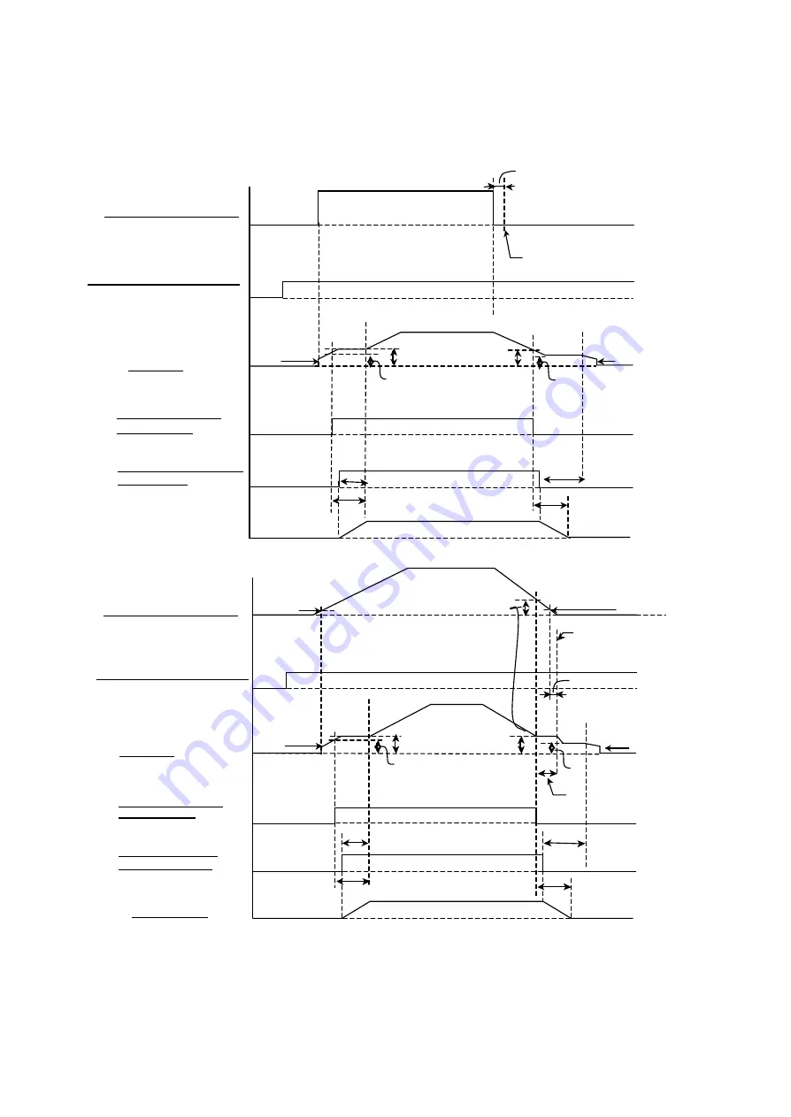
6.1.4 Brake Operations via Terminal A1 (Speed Command Input)
Time charts up to this point have been when the terminal A1 signal selection (H3-01) has been set to zero (0V to
+10V). There, the brake cannot be applied or released by using the Speed Command via terminal A1.
In the diagram below, H3-01 has instead been set to "1" (allowing input of -10V to +10V). This permits the brake to
be applied and released by using the Speed Command Input via Terminal A1.
Operations when H3 -01 (Terminal A1 Signal Level) is set to “1”:
When there are momentary changes to the Speed Command Input:
When there are smooth changes to the Speed Command Input:
Note: 1. If the Speed Command Input (terminal A1) is negative, t hen it is read as REV.
2. Once the Speed Command Input (terminal A1) value is smaller than b2 -01 and E1-09, then the Run Command will
be seen as open after 100ms has passed.
3. Until the Run Command is seen as open, the drive will operate with a speed command of either FRF (FRR) or FHF
(FHR), whichever is larger.
FWD Run Cmd Input (Trmnl S1 )
Speed Cmd Input (Trmnl A1)
Output Freq
Brake Release Cmd BR
(Trmnl M1-M2)
Brake Release Answer
back BX (Trmnl S5)
Brake Operation
closed
open
closed
open
closed
BT
BF
BDT
BDT
FHF(FHR)
FRF(FR
E1-09
HF
HT
Smaller of either
b2-01 or E1-09
closed
open
100 ms
Run Cmd was opened
by the timing found
here.
Note-3
Smaller of either
b2-01 or E1-09
Smaller of either
b2-01 or E1-09
FWD Run Cmd Input (Trmnl S1)
closed
open
closed
open
open
closed
BT
BF
BDT
BDT
FHF (FHR)
FRF (FRR)
Speed Cmd Input (Trmnl A1)
Output Freq
E1-09
Brake Release Cmd BR
(Trmnl M1-M2)
Brake Release Answer Back
BX (Trmnl S5)
HF
HT
Smaller of either
b2-01 or E1-09
closed
open
100 ms
Run Cmd was opened
by the timing found
here.
Содержание CIMR-F7Z
Страница 3: ......


