background image

OM 25-3503 us – Edition 4.1 * 2503_3503b550.fm

5-47

Wartung

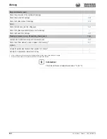
Information!

The maintenance meter starts at 500.0 hours. It counts down to 0.0 hours. A 
wrench symbol flashes as soon as the maintenance meter reaches this value.

Содержание 2503

Страница 1: ...Operator s Manual Track Excavator 2503 3503 Machine type E03 04 E03 07 Edition 4 1 Order no 1000255984 Language us 1 0 0 0 2 5 5 9 8 4 This Operator s Manual includeS The AEM PafETy J anual B 6...

Страница 2: ...this documentation which do not reflect products that have already been delivered and that will not be attached on these machines Technical data dimensions and weights are only given as an indication...

Страница 3: ...2 Preparing To Use The Machine 2 3 Conditions for use 2 3 User training and knowledge 2 3 Preparing for use 2 3 Information on visibility 2 4 Modifications and spare parts 2 4 Operator and Technician...

Страница 4: ...ding internal bombustion engines 2 17 Hydraulics 2 17 Noise 2 18 MSDS 2 18 Tracks 2 18 Battery 2 19 Safety Guidelines while using Internal Combustion Engines 2 19 Running the engine 2 19 Fueling the e...

Страница 5: ...tive structures 3 38 Definition of the term Protective Structure 3 38 Mechanical integrity 3 38 Definition of FOPS Front Guard levels 3 39 Responsibility for machine equipped with protective structure...

Страница 6: ...Control lever on the left 3 81 Auxiliary hydraulics proportionally controlled 3 81 Boom swivel controls proportionally controlled 3 81 Hammer operation proportionally controlled 3 82 Adjusting control...

Страница 7: ...Tier IV 3 109 Indication of load 3 111 Particulate matter catalyst indicator lights 3 111 Regeneration push button 3 112 Automatic regeneration mode 3 113 Manual regeneration 3 114 Malfunctions 4 Hydr...

Страница 8: ...aded fittings and attachments 5 27 Pivots and hinges 5 27 Lubrication points 5 27 Lubrication points on slewing cylinder ball bearing race of live ring 5 28 Lubrication points on the stabilizer blade...

Страница 9: ...5 Operating range 2503 3503 3503 VDS 6 5 Rotation speed of upper carriage 2503 3503 3503 VDS 6 5 Electrical system 6 6 Fuse box in cabin 6 6 Noise levels 6 6 Vibration 6 7 Coolant compound table 6 9...

Страница 10: ...ding and transporting 3 62 Overview 1 2 Maintenance Adding coolant 5 8 Adding engine oil 5 6 Adding hydraulic oil 5 16 Air filter 5 12 Biodegradable oil 5 17 Bleeding the fuel system 5 4 Checking the...

Страница 11: ...nstructions 2 1 General conduct 2 3 Identification 2 1 Seat adjustment 3 50 Backrest adjustment 3 51 Horizontal adjustment 3 51 Weight adjustment 3 51 Seat belt 3 52 Seat belt height adjustment 3 52 S...

Страница 12: ...I 10 OM 25 3503 us Edition 4 1 Ba2503_3503us4_0SIX fm Index...

Страница 13: ...rking is the best way to avoid accidents Operational safety and readiness of the machine do not only depend on your skill but also on maintenance and servicing of the machine This is why regular maint...

Страница 14: ...1 Boom light 2 Boom 3 Stick 4 Rubber tracks 5 Travel gear 6 Stabilizer blade 7 Cabin 8 Valve cover 9 Handhold Fig 1 Machine outside views 6 9 14 13 13 15 8 7 1 14 13 Exhaust pipe 14 Lifting eye tie d...

Страница 15: ...can be equipped with the Telematic option for transmitting operating data location etc via satellite Traveling drive The diesel engine permanently drives the twin axial variable displacement pump whos...

Страница 16: ...aximum payload stated in the lift capac ity table Information Please refer to the Operator s and maintenance manual of the attachment manufacturer for using and performing maintenance on attachments s...

Страница 17: ...95 m3 3 35 ft3 88 kg 194 lbs Offset bucket 850 mm 33 in 0 073 m3 2 58 ft3 110 kg 243 lbs Offset bucket 1000 mm 39 in 0 087 m3 3 07 ft3 121 kg 267 lbs 2503 with hydraulic Easy Lock quickhitch Bucket ty...

Страница 18: ...Offset bucket 1000 mm 39 in 0 111 m3 3 92 ft3 107 kg 236 lbs Offset bucket 1400 mm 55 in 0 158 m3 5 58 ft3 147 kg 324 lbs 3503 with mechanical Neuson quickhitch Bucket type Width Capacity Weight Bucke...

Страница 19: ...m3 4 77 ft3 106 kg 234 lbs Ditch cleaning bucket 1400 mm 55 in 0 158 m3 5 58 ft3 121 kg 267 lbs Offset bucket 1200 mm 47 in 0 129 m3 4 56 ft3 142 kg 313 lbs Offset bucket 1400 mm 55 in 0 150 m3 5 30 f...

Страница 20: ...ave proven their qualifications to the contractor Persons are expected to perform work reliably They have been appointed by the contractor for driving and servicing the earth moving machine Observe th...

Страница 21: ...nd Zertifizierungsstelle Fachausschuss Bauwesen Landsberger Str 309 80687 Munich Germany Distinguishing EU number 0515 Notified body involved in procedure T V S D Industrie Service GmbH Westendstr 199...

Страница 22: ...nd Zertifizierungsstelle Fachausschuss Bauwesen Landsberger Str 309 80687 Munich Germany Distinguishing EU number 0515 Notified body involved in procedure T V S D Industrie Service GmbH Westendstr 199...

Страница 23: ...ht Front GAWR Transport weight Rear GAWR Version Other information see chapter 6 Technical datac on page 6 1 17 digit serial number from 2012 For easier machine identification Wacker Neuson introduced...

Страница 24: ...ted on the chassis of the cabin at the upper left beside the door Front Guard type label The type label is located at the upper left of the chassis FOPS type label small screen The type label is locat...

Страница 25: ...ther side of the undercarriage Meaning Noise levels produced by the machine LWA sound power level Other information see chapter 6 5 Noise levels on page 6 6 Location Next to the cabin door Meaning Thi...

Страница 26: ...e cabin on the trim on the right Meaning Press the boom and the stabilizer blade into the ground as you leave the machine remove the starting key and place chocks on the left and right under the track...

Страница 27: ...f the engine compartment with the engine running 3 Perform work in the engine compartment at engine standstill only Location In the engine compartment Meaning The valve cover is opened with this Bowde...

Страница 28: ...witch on the control lever on the left control lever on the right with auxiliary hydraulics and proportional controls Location On the headliner see chapter 3 54 Powertilt option 3503 on page 3 97 WARN...

Страница 29: ...OM 25 3503 us Edition 4 1 2503_3503b110 fm 1 17 Introduction 1 10 Other signs and symbols from AG01598 Overview of safety labels...

Страница 30: ...th lifting devices slings chains or cables Location On either side of the stabilizer blade and on either side of the boom Description Tie down points Tie down points during transport to prevent moveme...

Страница 31: ...type label Meaning Interval at which lubrication point must be lubricated Location On upper carriage Meaning Position in which the ball type cock must be during hammer normal operation Location On the...

Страница 32: ...hydraulic oil reservoir Meaning The reservoir contains biodegradable hydraulic oil This label is notched on the side depending on the biodegradable hydraulic oil used 1 BP Biohyd SE S 46 2 Panolin HLP...

Страница 33: ...control levers Operating Pattern A ISO controls Europe and Operating Pattern A Check before starting the machine the operating pattern that has been chosen see chapter 3 46 Changeover valve for SAE I...

Страница 34: ...pening or removing the safety devices for example engine cover fan guard Location On the engine cover Description This safety label warns of the following dangers 1 Rotating fan Stay clear of the engi...

Страница 35: ...voir Meaning 1 CAUTION danger of being caught up 2 Always use the handles to open and close the front window 3 Always lock the front window with both locks Location On the front window Meaning option...

Страница 36: ...Description Accumulator is under high pressure Always read the Operator s Manual before performing maintenance or repairs Location On the upper carriage next to the accumulator Description Indicates...

Страница 37: ...Location In the engine compartment on the expansion tank Description 1 Operate only from the seat and fasten the seat belt to prevent falling out of the machine 2 Operate within the stability limits o...

Страница 38: ...e 6 14 see chapter 6 14 Lift capacity table 3503 on page 6 15 see chapter 6 16 Lift capacity table 3503 VDS on page 6 17 Location On the headliner Meaning option This label describes the functions of...

Страница 39: ...available as an option from Wacker Neuson A fire extinguisher according to DIN EN 3 must be installed by a Wacker Neuson service center A bracket for the fire extinguisher must be fastened on the C p...

Страница 40: ...1 28 OM 25 3503 us Edition 4 1 2503_3503b110 fm Introduction...

Страница 41: ...al consequences of the hazard Obey all safety messages that follow this symbol to avoid possible injury or death WARNUNG CAUTION CAUTION indicates a hazardous situation which if not avoided could resu...

Страница 42: ...he machine Wacker Neuson will not be liable for damage resulting from use other than mentioned above The user alone will bear the risk 3 Designated use also includes observing the instructions set for...

Страница 43: ...viceable condition and if necessary or required by law to require the operating or servicing persons to wear protective clothing and safety equipment User training and knowledge Always keep this Opera...

Страница 44: ...welding work on load bearing elements Spare parts must comply with the technical requirements specified by Wacker Neuson Contact your Wacker Neuson dealer for assistance 2 6 Operator and Technician Qu...

Страница 45: ...Never change the seat position when operating the machine Make sure that all safety devices are properly installed and functional before starting work Before putting the machine attachment into opera...

Страница 46: ...ment additional equipment or material The danger zone also includes the area affected by falling material equipment or constructions debris The danger zone must be extended by 0 5m 20 in in the immedi...

Страница 47: ...tified immediately Traveling Before moving the machine always check whether the supplementary equipment and the attachments have been safely stowed away or attached Careful when reversing the machine...

Страница 48: ...k may be performed by a Wacker Neuson dealer only Always replace the complete rollbar if it is deformed cracked or otherwise damaged If you are not sure always contact a Wacker Neuson dealer Traveling...

Страница 49: ...or death No drilling cutting or grinding Do not mount any brackets Do not perform any welding bonding work Replace the complete protective structure if it is damaged deformed and or cracked If you ar...

Страница 50: ...id tipping movements of the machine under all circumstances Operation in areas involving a risk of falling objects is prohibited Do not fasten the seat belt in order to be able to leave the machine im...

Страница 51: ...pressure on page 3 88 Operate the machine only if all protective devices for the attachments have been installed and are functional and if all brake light and hydraulic connections have been connecte...

Страница 52: ...r and have the error repaired immediately Working with a hammer NOTICE Always observe the following instructions Do not use the impact force of the attachment to perform demolition work Keep the hamme...

Страница 53: ...anual 2 14 Safety Guidelines for Maintenance General maintenance notes Operational readiness and the service life of machines are heavily dependent on maintenance It is therefore in the interest of th...

Страница 54: ...stopping procedures set forth in the Operator s Manual and the information on maintenance Prior to performing assembly work on the machine ensure that no movable parts will roll away or start moving...

Страница 55: ...forming maintenance and repairs After cleaning remove all covers and tapes applied for that purpose After cleaning examine all fuel lubricant and hydraulic oil lines for leaks chafe marks and damage R...

Страница 56: ...cure exposed lines Safely fasten lines if vibration or shocks to these lines must be avoided Overhead electric lines WARNUNG DANGER Personal injury hazard due to electrical shocks Will cause severe in...

Страница 57: ...follow the warnings and safety instructions can cause serious injury or death Keep the area around the exhaust system free of flammable materials Check the engine and fuel system to leaks loose fuel...

Страница 58: ...s MSDS When handling oil grease and other chemical substances such as battery electrolyte or hydraulic fluid observe the product related safety regulations Material Safety Data Sheet MSDS Be careful w...

Страница 59: ...l tank for leaks and cracks before starting the engine Do not run the machine if fuel leaks are present or the fuel lines are loose Engine exhaust CAN KILL YOU IN MINUTES Engine exhaust contains carbo...

Страница 60: ...cated on the exavator side of the hydraulic hose and must not be removed Do not squeeze hydraulic hoses Do not put hydraulic hoses over edges Do not put anything down on the hydraulic hoses Do not put...

Страница 61: ...xample 40 18 or 40 A used for identifying the control elements means fig no 40 control element no 18 or position A in fig no 40 Figures carry no numbers if they are placed to the left of the text The...

Страница 62: ...3 2 OM 25 3503 us Edition 4 1 2503_3503b320 fm Operation 2 15 7 17 9 1 16 11 20 23 22 24 25 6 19 21 18 12 14 10 5 3 8 26 28 12 13 27 29 30 31 32 Cabin top view up to serial no AG02452...

Страница 63: ...OM 25 3503 us Edition 4 1 2503_3503b320 fm 3 3 Operation 2 7 17 9 1 16 11 20 23 22 24 25 6 19 21 18 12 14 10 5 3 8 26 28 12 13 27 29 30 31 32 15 33 Cabin top view from serial no AG02453...

Страница 64: ...2027 16 Throttle 3 11 17 Stabilizer blade lever 3 4 18 Auxiliary hydraulics pedal 3 4 19 Preheating start switch 3 11 20 12 V power outlet2 2 Power outlet for cabin version 12 V connection for canopy...

Страница 65: ...OM 25 3503 us Edition 4 1 2503_3503b320 fm 3 5 Operation 35 38 34 36 37 39 40 43 42 48 46 51 44 47 41 Control elements on the left Control elements on the right 45 49 50 Up to serial no AG02452...

Страница 66: ...3 6 OM 25 3503 us Edition 4 1 2503_3503b320 fm Operation 35 38 34 36 37 39 40 41 Switch panel left Switch panel right 49 46 43 52 47 51 45 48 50 42 53 44 From serial no AG02453 Tier III...

Страница 67: ...ation 3 48 44 Safe load indicator option 1 3 102 45 Proportional controls status indicator option 3 82 46 Washer system 3 49 47 Rotating beacon option 3 37 48 Automatic engine speed setting option 3 1...

Страница 68: ...putting the machine into operation The machine may only be used in technically perfect condition in accordance with its designated use and the instructions set forth in the Operator s Manual and only...

Страница 69: ...llowing points before putting the machine into operation or starting the engine No Question 1 Enough fuel in the tank 5 2 2 Coolant level OK 5 8 3 Water drained from the water separator 5 4 4 Engine o...

Страница 70: ...alternator charge function gone out 3 12 3 Temperature gage for engine coolant in normal range 3 13 4 Accelerator pedals working correctly 3 27 No Question 1 Attachments lowered to the ground 3 76 2...

Страница 71: ...6 controls the engine speed progressively as follows Push throttle 16 upward A Engine speed is increased Push throttle 16 down B Engine speed is reduced 1 0 2 3 Fig 75 Preheating start switch 19 Posit...

Страница 72: ...illuminate until the operating temperature is reached 35 Indicator light red alternator charge function NOTICE The coolant pump no longer runs if the V belt is faulty Risk of engine overheating or br...

Страница 73: ...old starter indicator light yellow Illuminates if the key in the preheating start switch is in position 2 A glow plug preheats the air in the combustion chamber of the engine when the key is in this p...

Страница 74: ...s required maintenance or possible machine malfunctions Information After switching on the starter the indicator lights are checked during the first 2 seconds and the current reading of the maintenanc...

Страница 75: ...Engine warning 4 4 3 111 6 Yellow PMC regeneration 3 109 3 111 7 Red Engine oil pressure 4 4 8 Yellow Preheating 3 22 9 Red Charge indicator light 3 22 4 5 10 Red not assigned 11 Red Coolant temperat...

Страница 76: ...ash system switch 3 49 25 Ventilation heating switch 3 48 26 Working light switch 3 36 27 Rotating beacon option switch 3 37 28 Safe load indicator switch option 3 102 No Symbol Color Designation See...

Страница 77: ...e oil pressure Engine number 4 6 Setting of display brightness 3 19 Setting of display contrast Setting of time date Replace the hydraulic oil filter Dirty air filter 5 11 Dirty hydraulic oil radiator...

Страница 78: ...to 0 0 hours The wrench symbol then starts to flash The maintenance meter keeps on counting down 0 1 hours 0 2 hours etc Information After 500 operating hours the output of the Tier IV diesel engine...

Страница 79: ...0 fm 3 19 Operation Multifunctional display Tier IV only Display element buttons A selection button B to next menu page set Menu structure of display setting Information The software version number is...

Страница 80: ...ton A Display adjustment menu The selected menu level is marked with an arrow Press push button A 1 x brightness Press push button A 2 x contrast Press push button A 3 x time date Adjusting brightness...

Страница 81: ...the contrast Setting the time or date Adjustment sequence year month day hours minutes Press push button B to access the adjustment mode Press push button A to set or to access the next setting month...

Страница 82: ...re than 10 seconds Wait about 1 minute so the battery can recover before trying again Procedure NOTICE Actuating the preheating system too long can damage the preheater Never preheat the engine more t...

Страница 83: ...icator lights illuminate Replace malfunctioning indicator lights immediately Turn the starting key to position 2 and hold it in this position for about 5 seconds The intake air is preheated Turn the s...

Страница 84: ...0 and remove master key B Now insert the new key or the key requiring coding in the starter and turn it to position 1 within 15 seconds This action registers the key The procedure is automatically ca...

Страница 85: ...to warm up at slightly increased idling speed until it reaches its operating temperature of 70 C 158 F coolant Run the engine with no load during the warm up phase raise control lever base on the lef...

Страница 86: ...ing battery Connect the other end of the black cable to a solid metal component fimly screwed on the engine block or onto the engine block itself Do not connect it to the negative ter minal of the emp...

Страница 87: ...el path Before starting machine travel on a construction site align the upper car riage so that the operator has an unrestricted view of the travel path DANGER Accident hazard The machine moves in the...

Страница 88: ...330 fm Operation Forward or reverse travel speed depends on the position of the drive levers or accelerator pedals Information Ensure that both tracks move as you change direction otherwise the rubber...

Страница 89: ...machine handling when cor nering High speed 3503 Auto 2 Speed Switch 42 activates the Auto 2 Speed function The switch is located on the control lever console on the left The machine now moves at hig...

Страница 90: ...ve levers or the accelerator pedals Stabilizer blade as a parking brake The stabilizer blade is used as a parking brake Press the stabilizer blade against the ground 3 21 Machine travel on slopes DANG...

Страница 91: ...ne speed The machine can slip even on gentle slopes if it travels across grass leaves humid metal surfaces frozen ground or ice Preparations for performing machine travel on slopes Always move straigh...

Страница 92: ...the center of the machine Do not exceed a maximum sloping angle of 15 Lateral angle of inclination Do not exceed a maximum lateral angle of inclination of 10 On lateral inclinations over 10 pile up ma...

Страница 93: ...n Check the position of the stabilizer blade before driving the machine Always set the slewing stabilizer blade option 3503 to the straight position The only exception that can be made to this is for...

Страница 94: ...chine rolling away under its own weight after parking it Can cause serious injury or death Press the boom and the stabilizer blade against the ground Park the machine on level ground Secure the tracks...

Страница 95: ...the machine on slopes Avoid stopping the machine abruptly Always ensure that there is enough space for stopping the machine Park the machine on level ground with sufficient bearing capacity Never park...

Страница 96: ...ne operation only switch the working lights on when no one can be blinded by it The working light illuminates in the first position the roof lights illuminate too in the sec ond position Information T...

Страница 97: ...o stay in the danger zone Do not rely on the travel signal under any circumstances If the travel signal does not sound stop machine operation immediately and con tact a Wacker Neuson service center ob...

Страница 98: ...res is prohibited Have a damaged cabin or protective structure immediately replaced DANGER Accident hazard during machine travel without cabin canopy Performing machine travel without cabin canopy cau...

Страница 99: ...against heavy falling objects FOPS or heavy objects penetrating into the cabin from the front Front Guard such as trees pieces of rock for machines that are used for clearance work demolition work an...

Страница 100: ...ensure that the hazard situation is evaluated and that the national regulations are observed The machine owner must ensure that only work is performed that does not require any higher protection Acci...

Страница 101: ...structure Information The protective FOPS structure corresponds to category I according to ISO 3449 1992 The machine owner must ensure that the hazard situation is evaluated and that the national regu...

Страница 102: ...machine Stop the engine 2 A minimum 2 persons are required for installing removing 3 Front and rear fastening points A 4 Tighten screws B and lock nuts on the left and right to 45 Nm 33 ft lbs Fig 118...

Страница 103: ...ation The protective Front Guard structure corresponds to category I according to ISO 10262 1998 The machine owner must ensure that the hazard situation is evaluated and that the national regulations...

Страница 104: ...4 OM 25 3503 us Edition 4 1 2503_3503b330 fm Operation 4 Mounting point B lower 5 Tighten screws C and lock nuts at the upper and lower left and right to 110 Nm 81 ft lbs Fig 122 Lower mounting point...

Страница 105: ...Accident hazard in conditions of restricted visibility due to rain snow fall dust etc Causes serious injury or death Stop machine operation immediately Information The shatter protection canopy option...

Страница 106: ...nd park the machine Stop the engine 2 Install remove shatter protection B from the front and fasten remove it at the fas tening points C with the fastening material supplied 3 Tighten screws D at fast...

Страница 107: ...an exit in an emergency Warning WARNING Injury hazard due to glass splinters Injury hazard due to glass splinters when smashing the window with the emergency hammer Only smash windows in an absolute...

Страница 108: ...e to rotating parts Can cause serious injury or death Stop the engine Open the engine cover only if the engine is at a standstill Adjust cabin temperature as follows Open the engine compartment Turn b...

Страница 109: ...r Refer to the antifreeze instructions for further information on concentrations The rubber diaphragm in the non return valve in the housing conglutinates if stored in a dry condition over a longer pe...

Страница 110: ...fore starting machine travel see chapter 3 8 Before starting the engine on page 3 22 NOTICE Adjusting the backrest can damage the rear window and the removable part of the front window Ensure that the...

Страница 111: ...pring action Press the lever down More spring action Press the lever up Horizontal adjustment Sit down on the operator seat Pull lever 7 upward and at the same time Move the seat forward or backward B...

Страница 112: ...func tioning Seat belt buckle must not be obstructed by foreign bodies paper or sim ilar otherwise the buckle latch cannot lock into place After an accident the belt strap is stretched and no longer...

Страница 113: ...ckle B by spring pressure Slowly return the seat belt to the retractor Longer shorter seat belt adjustment Lengthen the seat belt as follows Hold buckle latch A at a right angle to the seat belt and p...

Страница 114: ...unintentional operation or movement of the machine Open the front window as follows The front window is fitted with handles and small levers on either side Push levers A upward on either side Pull th...

Страница 115: ...ess door lock A Locking the door Turn the key in door lock A to the left L The door is locked Unlocking the door Turn the key in door lock A to the right R The door is unlocked Opening the door from t...

Страница 116: ...g the door opener Turn button E to the right to release the door from the arrester Opening the side window Press button F up At the same time move the window to one of the positions marked with seven...

Страница 117: ...se handle A on the A pillar Use track C for access Exit Park the machine see chapter 3 23 Parking the machine on page 3 34 Use handle A on the A pillar Use track C to leave the cabin Machines up to se...

Страница 118: ...36 Valve compartment cover Canopy Opening Unlock the lock with starting key B Pull out handle C Open the valve compartment cover upward Closing Firmly close the valve compartment cover until the lock...

Страница 119: ...s functional A malfunctioning machine must be loaded with a crane If necessary contact a Wacker Neuson service center for towing the machine away Fasten the towing equipment only on the towing eye pro...

Страница 120: ...and L2 Set the slewing stabilizer blade option 3503 straight Warning WARNING Injury hazard when loading and transporting Can cause serious injury or death See chapter Safety section 2 7 Information T...

Страница 121: ...the control lever base 14 Remove the starting key and carry it with you 15 Remove all loose objects from inside the machine 16 Leave the cabin close and lock all doors windows and covers 17 Install su...

Страница 122: ...ction of this manual Do not attempt to lift the excavator with any type of crane including wheel load ers unless the crane operator is qualified to lift loads in craning operations The crane operatpr...

Страница 123: ...e Before transporting the machine through heavy rain close the outlet of the exhaust silencer with a simple cap or suitable adhesive tape Ensure that the driver of the transport vehicle knows the over...

Страница 124: ...ing gear is taut Remove central plug B X28 from the cabin wiring Central plug B is located at the rear right next to the seat in the cabin Remove the hose of the washer fluid tank from non return valv...

Страница 125: ...he machine as follows Do not allow anyone to stay in the cabin and close the doors and the engine cover Slowly raise the cabin NOTICE Inspect the cabin for damage as you raise it Set down the cabin sa...

Страница 126: ...it Connect central plug B X28 with the cabin wiring Connect the hose of the washer fluid tank with non return valve C Information Installing non return valve C is not necessary if the machine is equip...

Страница 127: ...1 2503_3503b330 fm 3 67 Operation Raise the floor mat on either side Tighten screws F to 87 Nm 64 ft lbs Put the floor mat back in place on either side Fig 166 Left cabin attachment F Fig 167 Right s...

Страница 128: ...ork The building can collapse causing serious injury and damage In general the machine is more liable to tilt if the attachment is positioned laterally than if it is positioned at the front or rear of...

Страница 129: ...buttons B and C about 5 seconds without moving the joysticks to unlock The Wacker Neuson Vario feature has four lock positions at offset positions of 90 each 0 360 90 180 270 Press the joystick on th...

Страница 130: ...h the Wacker Neuson Vario feature Danger zone of the Wacker Neuson Vario feature Warning WARNING Crushing hazard in the danger zone of the Vario feature Can cause serious injury or death Do not allow...

Страница 131: ...Reach can be improved with the Wacker Neuson Vario feature The bucket can be moved up to the stabilizer blade by repositioning the upper carriage to the side opposite the blade 3 45 Control levers IS...

Страница 132: ...e handle of ball type cock E toward F when using the auxiliary hydraulics Actuating the auxiliary hydraulics Oil flow left Press hammer pedal 18 backward Oil flow right Press hammer pedal 18 forward F...

Страница 133: ...ion during hammer operation see chapter Shatter protection option on page 3 45 If the machine is equipped with a cabin option the front window must be closed Warning WARNING Danger of piercing penetra...

Страница 134: ...ent is used Never turn lower or set down the attachment abruptly Do not extend or retract the boom abruptly Do not use the impact force of the attachment to perform demolition work Broken or falling p...

Страница 135: ...unit beyond 30 during hammer operation oth erwise the load on the boom increases enormously Stop machine operation immediately if a hydraulic hose moves back and forth in an unusual manner The pressu...

Страница 136: ...1 Press forward and hold the control lever A and E Until the boom is completely lowered Return the control lever to neutral Fig 181 Control lever on the right H G E F Position Lever Function E Forward...

Страница 137: ...irectional valve Control lever on the left SAE controls Control lever on the right SAE controls Fig 184 Control lever on the left SAE controls D C A B 1 Position Lever Function A Forward Boom is lower...

Страница 138: ...ls and vice versa Changing over Loosen the wing nut and set the valve to the required position Retighten the wing nut after changing over NOTICE No machine travel or operation if wing nut J is malfunc...

Страница 139: ...recommend setting the controls to the low characteristic curve 1 slow movements The slide switch is not pressed fully in this position and you can move the machine more smoothly flat characteristic c...

Страница 140: ...between moving hydraulic components and fixed obsta cles Crushing hazard The operator of the machine or hydraulic system must be aware of possible machine or system errors Information Proportional con...

Страница 141: ...iliary hydraulics Oil flow left Move slide switch B to the left Oil flow right Move slide switch B to the right Boom swivel controls proportionally controlled Changing over to swivel controls Pressing...

Страница 142: ...imum throughput Disengage the starter Then move slide switch B to the right C Hold slide switch B to the right C and switch on the starter at the same time Then release slide switch B Indicator light...

Страница 143: ...the left L and right R forward until the boom is completely lowered Return the control levers on the left L and right R to neutral position Fig 198 Control lever on the right H G E F Position Lever Fu...

Страница 144: ...The upper carriage rotates to the left Rotate the upper carriage to the right as follows Push the control lever on the left 1 to the right B The upper carriage rotates to the right Swivel unit brake...

Страница 145: ...blade as far as it will go 3 Swivel the boom to the left as far as it will go 4 Turn the upper carriage so that the boom is 90 to the travel gear 5 Position the boom as shown in Fig 206 6 Stop the eng...

Страница 146: ...ttachment 10 Wait one minute If the attachment does not move from the piece of wood Machine is operational If the attachment moves away from the piece of wood Stop operation immediately Contact a Wack...

Страница 147: ...diate vicinity of a wall or parts of a building ensure that the upper carriage does not touch anything when it is tilted On a slope position the machine so that the upper carriage is tilted toward the...

Страница 148: ...tions of the system and hydraulic lines that are to be opened before starting setup or repair work for example fitting removing an attachment Releasing pressure Release the pressure as follows Park th...

Страница 149: ...given in the Operator s Manual of the attachment Also refer to the Operator s Manual of the attachment for the procedure to follow for fitting an attachment onto a quickhitch Specific safety instructi...

Страница 150: ...he bucket only with minimum pressure on the ground as you remove the pins The higher the pressure on the ground the higher the resistance and the more difficult it is to remove the pins Installing a b...

Страница 151: ...s follows Approach the machine to the attachment Hitch coupling bar M onto coupling claws L of the quickhitch to pick up the bucket Engage lock mechanism N in mounting bores O Place the bucket on leve...

Страница 152: ...e off and cause serious injury or death Do not allow anyone to stay in the danger zone Do not use damaged attachments Check pin F must be fully retracted Otherwise repeat the lock cycle until check pi...

Страница 153: ...the attachment touches the quickhitch 3 Move the attachment inward completely 4 Unlock switch D and press it to position 1 The quickhitch is enabled and the buzzer sounds 5 Press and hold the foot op...

Страница 154: ...ion 6 Release the stabilizer blade lever and foot operated push button E The quickhitch closes Check pin F must be fully retracted 7 Press switch D to position 2 The quickhitch is disabled and the buz...

Страница 155: ...he ground 2 Press switch D to position 1 The quickhitch is enabled and the buzzer sounds 3 Press and hold the foot operated push button E and pull the stabilizer blade lever backward at the same time...

Страница 156: ...itch D to position 2 The quickhitch is disabled and the buzzer does not sound any longer Shovel bucket operation With some restrictions Wacker Neuson backhoe buckets can also be used for shovel bucket...

Страница 157: ...stic or optical warning device see chapter 3 57 Safe load indicator option on page 3 102 The machine is equipped with a hose burst valve see chapter Safety fea ture Hose burst valve option on page 3 1...

Страница 158: ...Installing the Powertilt unit Proceed as follows Lower the Powertilt unit to the ground with its flat side facing down Grease the joints and the pins before inserting them Start the engine Straighten...

Страница 159: ...rtilt unit The following connections are possible 3rd control circuit with quick connect coupling Two different connection sizes each Connection of line between boom 1 and connection 1 on the Powertil...

Страница 160: ...e right Information The auxiliary hydraulics pedal is locked The auxiliary hydraulics is operated via the control lever on the left see chapter Control lever on the left on page 3 81 3 55 Connections...

Страница 161: ...he ball type cocks to position B Release the pressure in the hydraulic system see chapter 3 50 Releasing the pres sure on the operating hydraulics on page 3 88 The grab can now be coupled onto couplin...

Страница 162: ...ollows Reduce reach until both the acoustic signal and the indicator light in the display ele ment go out The switch position can vary depending on version see Switch panel right on page 3 14 Safety f...

Страница 163: ...e This can damage the machine and or the attachment Working with the drive force Never ram the attachment into the ground to dig during machine travel This can damage the machine and or the attachment...

Страница 164: ...as you retract attachments for driving or transport Fully lowering the stabilizer blade Fully lower the stabilizer blade when using it on the side opposite the excavation side No thrusting the stabili...

Страница 165: ...upward and not to be filled com pletely This slows down work too Dig as follows Penetrate into the ground with the bucket E Lower the stick and at the same time align bucket E until reaching the requi...

Страница 166: ...isibility for the driver of the exca vator Loading material on trucks is easier and faster if the hydraulic excavator is placed at the rear end of the truck and not at the sides Grading Use the stabil...

Страница 167: ...ou perform deep excavations with stabilizer blade B at the front ensure that piston rod A does not touch or rest on stabilizer blade B Fig 254 Stabilizer blade at rear Warning WARNING Tipping hazard o...

Страница 168: ...steep slope Loading vehicles When loading vehicles we recommend taking the following into account If possible the vehicle and the working direction of the bucket should form an angle of 45 Raise the f...

Страница 169: ...is called regeneration Regeneration takes about 30 minutes The more often the automatic regeneration mode is corrected or modified the longer regeneration takes If the dirt in the particulate matter c...

Страница 170: ...ation as early as possible Do not ignore the highest load indication Information The load is the contamination level of the particulate matter catalyst Among other things this level depends on the loa...

Страница 171: ...equired Regenera tion disa bled Description Yellow Red Yellow Yellow Yellow On On On On On After switching on the starter the indicator lights are checked during the first two seconds Off Off Off Off...

Страница 172: ...regeneration 2 automatic regeneration mode middle position 3 re activation of automatic regeneration Indicator lights Three indicator lights indicate the regeneration status B Regeneration required T...

Страница 173: ...s reached a certain contamination level indicator light B illuminates and an automatic regeneration is performed soon Indicator light C illuminates in addition during regeneration Information The mach...

Страница 174: ...tion Press and hold the Regeneration push button at least 3 seconds in position 1 NOTICE Possible damage to engine or particulate filter Perform a complete regeneration cycle NOTICE Fire hazard in the...

Страница 175: ...fuse 6 6 Engine starts but does not run smoothly or faultless Fuel grade does not comply with specifications 5 35 Dirty fuel filter Wrong valve clearance Injection line leaks Malfunctioning fuel injec...

Страница 176: ...inclination too high 3 30 Engine smoke Blue Oil level too high wrong oil 5 5 Machine inclination too high 3 30 White Engine starting temperature too low Fuel grade does not comply with specifications...

Страница 177: ...Malfunctioning decompression valve Oil escapes from the seals Powertilt turns only in one direction Malfunctioning internal decompression valve Both lines are connected to either the P1 or P2 connect...

Страница 178: ...er Neuson service center Flashes On Engine is about to be shut down or is already shut down Stop the engine immediately and contact a Wacker Neuson service center Engine warning Engine stop Oil pres s...

Страница 179: ...or light goes out after about one minute If the malfunction is still indicated stop the engine immediately and contact a Wacker Neuson service center The battery is no longer charged Coolant temperatu...

Страница 180: ...ited in case of major errors Engine power is reduced The traveling drive is disabled Stop and park the machine Contact a Wacker Neuson service center and have the malfunction rectified Machine travel...

Страница 181: ...culate matter catalyst errors No error If there is no error the marked symbol appears in the service tool Engine error machine status particulate matter catalyst data The corresponding symbol flashes...

Страница 182: ...4 8 OM 25 3503 us Edition 4 1 2503_3503b410 fm Malfunctions...

Страница 183: ...ecifically trained operator All other maintenance must be per formed by trained and qualified personnel only The maintenance plans indicate when the maintenance mentioned below must be per formed see...

Страница 184: ...a suitable container to collect the fuel as it drains and dispose of it in an environmentally friendly manner Information Do not run the fuel tank completely dry Otherwise air is drawn into the fuel...

Страница 185: ...an environmentally friendly manner Filler inlet A for the fuel tank is located in the valve compartment on the left in travel direction Proceed as follows Open filler inlet A Pump out the fuel with a...

Страница 186: ...to the OFF mark Fuel supply is interrupted Turn ball type cock B to the ON mark Fuel supply is open again Check the water separator as follows If the red indicator ring has risen to position C Stop th...

Страница 187: ...ecking the oil level Information Check the oil level once a day We recommend checking it before starting the engine After stopping a warm engine wait at least 5 minutes before checking Proceed as foll...

Страница 188: ...slowly so it can go down without entering the intake system Proceed as follows Clean the area around oil filler cap B Tier III or C Tier IV with a lint free cloth Open filler cap B Tier III or C Tier...

Страница 189: ...fore Check the coolant level at regular intervals Refer to the maintenance plans in the appendix for the intervals If coolant must be added frequently check the cooling system for leaks and or con tac...

Страница 190: ...es and clothing Turn filler cap B to the first notch and release the pressure Ensure that the coolant temperature is sufficiently low so you can touch the radiator plug with your hands Warning WARNING...

Страница 191: ...r A and on the radiator If the coolant level is below the LOW seam or if there is no coolant at the radiator s filler inlet Add coolant Tier IV check the coolant level on sight glass B If the coolant...

Страница 192: ...lant level must be between the Low and Full reservoir seams If necessary add coolant and repeat the procedure until the coolant level remains constant Information Check the antifreeze every year befor...

Страница 193: ...e damage do not clean inside filter C but replace it as indicated in the maintenance plan NOTICE Filter cartridges degrade prematurely when in service in acidic air for longer periods of time This ris...

Страница 194: ...ve outside filter B with slightly turning movements Ensure that all dirt dust inside the upper and lower housing sections F and E including dust valve G has been removed Clean the parts with a clean l...

Страница 195: ...e cloth to prevent dust from entering the engine Ensure that all dirt dust inside the upper and lower housing sections F and E including dust valve G has been removed Clean the parts with a clean lint...

Страница 196: ...serious injury or damage to property Interrupt work immediately if loose nuts or damaged hoses and lines are detected Contact your Wacker Neuson dealer immediately Replace the hose or line if one of...

Страница 197: ...ight swiveling cylinder Release the pressure in the operating hydraulics see chapter Releasing pressure on page 3 88 Stop the engine remove the starting key and carry it with you Raise the control lev...

Страница 198: ...and boom cylinders lower the boom and the bucket teeth to the ground Lower the stabilizer blade to the ground Set the boom straight swiveling cylinder Release the pressure in the operating hydraulics...

Страница 199: ...remaining amount of initial hydraulic fluid in the hydraulic system does not exceed 8 when changing biodegradable oil manufacturer indications Do not add mineral oil the content of mineral oil should...

Страница 200: ...ed lines Never weld or solder damaged or leaking pressure lines and threaded fittings Replace damaged parts with new ones Have damaged flexible lines replaced by a Wacker Neuson service center only Le...

Страница 201: ...and park the machine Stop the engine Raise the machine evenly and horizontally by means of the boom and stabi lizer blade Rubber track Position the machine so that mark B of the rubber track is in the...

Страница 202: ...ervice center if this does not reduce track tension NOTICE Excessive tension of the tracks causes serious damage to the cylinder and the track Tighten the tracks only up to the prescribed measuring di...

Страница 203: ...l size must not be worn more than 5 max tolerance Measurement can be performed with the accuracy of a slide gage Welding is prohibited Load hook wear Have load hooks Powertilt Powertilt for Easylock w...

Страница 204: ...ery can burst or explode Replace the battery immediately Avoid open flames and sparks and do not smoke near open battery cells otherwise the gas produced during normal battery operation can ignite Use...

Страница 205: ...uses Blown fuses indicate overloading or short circuits The electrical system must therefore be checked before installing the new fuse Only use fuses with the specified load capacity amperage see chap...

Страница 206: ...battery and do not smoke Do not attempt to jump start the machine if the battery is frozen or if the acid level is low The battery can burst or explode Replace the battery immediately Disconnect the...

Страница 207: ...use flammable liquids such as gasoline or diesel Cleaning with compressed air Work carefully Wear safety glasses and protective clothing Do not aim the compressed air at the skin or at other people Do...

Страница 208: ...t which remains fitted in the machine only with a mild soap solution do not use chemical agents as they can destroy the fabric Exterior of the machine The following articles are generally suitable Hig...

Страница 209: ...th and pin fastenings on the attachment Retighten loose connections immediately Contact a Wacker Neuson service center if nec essary Pivots and hinges All mechanical pivot points on the machine for ex...

Страница 210: ...race of live ring lubricate every 50 o h or once a week Lubricating the ball bearing race of the live ring 1 Drive the machine over a pit 2 Lower the stabilizer blade to the ground 3 Lower and suppor...

Страница 211: ...week Lubricating the teeth of the live ring Warning WARNING Crushing hazard Do not tilt or rotate the upper carriage dur ing lubrication Can cause serious injury or death Do not rotate the upper carr...

Страница 212: ...o lubrication point C with five strokes of the grease gun 6 Start the engine raise the boom and the stabilizer blade 7 Rotate the upper carriage by 90 8 Repeat steps 2 7 three times until the upper ca...

Страница 213: ...grease to lubrication point D with five strokes of the grease gun 6 Start the engine raise the boom and the stabilizer blade 7 Rotate the upper carriage by 90 8 Repeat steps 2 7 three times until the...

Страница 214: ...t can be hitched correctly by removing all dirt on either claw of the quickhitch Perform maintenance on the quickhitch once a day with the other maintenance for the machine Perform visual checks for p...

Страница 215: ...e battery and perform battery maintenance at regular intervals Close the exhaust pipe and the air intake opening of the air filter system Information Store the machine indoors if possible If storing t...

Страница 216: ...was out of service for over 6 months change the oil in the gearbox engine and other units Also replace hydraulic oil filters return and breather filters if the machine has been out of service for ove...

Страница 217: ...EES PANOLIN HLP Synth 46 BP BIOHYD SE S 46 Roller and friction bearings Grease KF2K 205 5 SKPF2K 20 lithium saponified grease according to DIN 51502 ISO 6743 9 Year round As required Live ring ball be...

Страница 218: ...owing intervals Information Please refer to the maintenance plan on page 5 38 for additional maintenance Engine oil grade Ambient temperature C C 20 15 10 5 0 5 10 15 20 25 30 35 40 SAE 10W SAE 20W SA...

Страница 219: ...e Oil grades for the hydraulic system depending on temperature Hydrau lics oil grade Ambient temperature HVLP1 C 20 15 10 5 0 5 10 15 20 25 30 35 40 50 ISO VG32 ISO VG46 ISO VG68 F 4 5 14 23 32 41 50...

Страница 220: ...d filter changes check oil levels after test run Engine oil 1 Engine oil filter 2 Fuel filter 3 Air filter element as indicated by the indicator light Coolant Hydraulic oil filter insert 4 Hydraulic o...

Страница 221: ...and function Check preheating system and electric connections Check correct function of air filter contamination gage Pressure check of primary pressure limiting valves Check tracks for cracks and cu...

Страница 222: ...for 1 minute 10 Lubrication service Lubricate the following assemblies components Live ring ball bearing Teeth of live ring Stabilizer blade swiveling stabilizer blade Swiveling console Swiveling cyli...

Страница 223: ...ngine compartment for damage Check the cabin and protective structures for damage for example the front guard FOPS Check the tracks for cracks and cuts Check the travel gear for damage for example the...

Страница 224: ...50 o h then every 500 o h 5 Replace the hydraulic oil the first time after 500 o h then every 1000 o h 6 Drain the gearbox oil the first time after 50 o h then every 1000 o h 7 Clean the water ducts e...

Страница 225: ...structures for example the cabin for tightness Clean the lights light system signaling system Option Check the acoustic warning device of the overload valve Easy Lock check the acoustic warning system...

Страница 226: ...eck the Powertilt for damage 3 97 Weekly maintenance every 50 operating hours user Page Lubricate the machine according to the lubrication plan 5 27 Check the air filter element clean or replace it if...

Страница 227: ...s Wacker Neuson service center Change the engine oil Replace the engine oil filter Replacing the fuel filter Replace the water separator prefilter element Replace the hydraulic oil filter insert Repla...

Страница 228: ...replacement according to the dirt indicator every 1000 o h or once a year at the latest Replace after 50 o h when in extensive use in environments with acidic air such as acid production facilities st...

Страница 229: ...03 us Edition 4 1 2503_3503b550 fm 5 47 Wartung Information The maintenance meter starts at 500 0 hours It counts down to 0 0 hours A wrench symbol flashes as soon as the maintenance meter reaches thi...

Страница 230: ...5 48 OM 25 3503 us Edition 4 1 2503_3503b550 fm Wartung...

Страница 231: ...ble variable displacement gear pump Flow rate 28 8 28 8 19 2 l min 7 6 gal 7 6 gal 5 0 gal min Operating pressure for operating and travel hydraulics 240 bar 3 481 psi Swivel unit operating pressure 2...

Страница 232: ...nd stroke 88 x 90 mm 5 4 x 5 5 in Power 23 7 kW 31 8 hp Max torque intermittent 143 Nm 1200 rpm 105 ft lbs 1 200 rpm Max engine speed without load 2025 rpm Idling speed 1100 rpm Fuel injection system...

Страница 233: ...over subgrade 410 mm 16 in 385 mm 15 in Scraping depth 480 mm 19 in 529 mm 21 in Tilting angle 25 Operating hydraulics Model 3503 Max operating pressure 240 bar 3 481 psi Main pressure restriction fo...

Страница 234: ...404F 22 Design Water cooled diesel engine Number of cylinders 4 cylinders Displacement 2216 cm 135 in Nominal bore and stroke 84 x 100 mm 3 3 x 3 9 in Power 29 8 kW at 1975 rpm 40 0 hp at 1975 rpm Ma...

Страница 235: ...stick 240 bar 3 481 psi Main pressure restriction for stabilizer blade 210 bar 3 046 psi Main pressure restriction for pilot control pressure 35 bar 508 psi Main pressure restriction for swivel drive...

Страница 236: ...5 Heating horn 5 10 Valves travel signal 6 10 Window wiper cabin 7 10 Alternator 8 15 Spare 9 10 Rotating beacon radio 12 V power outlet antitheft protection 10 15 Socket 11 10 Spare Sound power level...

Страница 237: ...environmental factors to the average vibration level in order to obtain the estimated vibration level Note For further vibration indications refer to the indications in ISO TR 25398 Mechanical Vibrati...

Страница 238: ...ne travel across rough terrain Reduce vibration to a minimum during long work cycles or during machine operation over long distances Use a machine with a suspension system for example on the operator...

Страница 239: ...es This chapter summarizes part of the legal regulations However its aim is not to replace the original references Other parts of this document are based on information of the United Kingdom Health an...

Страница 240: ...65 kg 143 3 lbs Drive torque at 210 bar 3045 psi 2990 Nm 2 205 ft lbs Holding torque at 225 bar 3263 psi 7270 Nm 5 362 ft lbs Minimum hose pipe size Connecting hose size 10 mm 0 4 in 6 mm 0 25 in Type...

Страница 241: ...ck 2000 mm 79 in Max digging height 4125 mm 13 6 Max digging height long stick 4250 mm 13 11 Max tilt out height 2925 mm 9 7 Max tilt out height long stick 3080 mm 10 1 Max digging radius 4515 mm 14 1...

Страница 242: ...ight 3620 mm 11 11 3723 mm 12 3 Max dump height with long stick 3810 mm 12 6 3923 mm 12 10 Max digging radius 5270 mm 17 3 5100 mm 5440 mm 16 9 17 10 Max digging radius with long stick 5546 mm 18 2 52...

Страница 243: ...ng height long stick 5220 mm 17 2 Max tilt out height 3735 mm 12 3 Max tilt out height long stick 3935 mm 12 11 Max digging radius 5270 mm 17 3 Max digging radius long stick 5546 mm 18 2 Max reach at...

Страница 244: ...A 3 5 m 11 5 3 0 m 9 8 2 5 m 8 2 2 0 m 6 6 B 3 0 m 9 8 415 915 415 915 400 882 400 882 2 0 m 6 6 410 904 350 772 410 904 380 838 420 926 420 926 460 1 014 460 1 014 1 0 m 3 3 425 937 310 683 460 1 01...

Страница 245: ...ded A 4 5 m 14 8 3 5 m 11 5 2 5 m 8 2 1 5 m 4 9 B 3 0 m 9 8 800 1 764 545 1 202 745 1 642 685 1 510 2 0 m 6 6 840 1 852 480 1 058 870 1 918 660 1 455 1110 2 447 1105 2 436 1 0 m 3 3 890 1 962 415 915...

Страница 246: ...951 1 0 m 3 3 890 1 962 580 1 279 335 739 900 1 984 600 1 323 345 761 1100 2 425 870 1 918 500 1 102 1795 3 957 1395 3 075 800 1 764 0 0 m 0 0 955 2 105 590 1 301 335 739 955 2 105 590 1 301 335 739...

Страница 247: ...4 5 m 14 8 3 5 m 11 5 2 5 m 8 2 1 5 m 4 9 B 3 0 m 9 8 800 1 764 650 1 433 750 1 653 550 1 213 2 0 m 6 6 845 1 863 350 772 900 1 984 530 1 168 1210 2 668 890 1 962 1 0 m 3 3 900 1 984 340 750 900 1 98...

Страница 248: ...t must be subtracted from the weight or mass value specified in the table Use the machine for lifting gear applications only if the mandatory lifting gear and safety equipment is installed functional...

Страница 249: ...stem s stabilizing features Neither 75 of the static tilt load nor 87 of the hydraulic lift capacity is exceeded Calculation basis according to ISO 10567 Setting pressure on boom cylinder 24 000 kPa 3...

Страница 250: ...6 20 OM 25 3503 us Edition 4 1 2503_3503b610 fm Technical datac 2503 3503 long short stick...

Страница 251: ...OM 25 3503 us Edition 4 1 2503_3503b610 fm 6 21 Technical datac 3503 long short stick VDS 3503 long short stick Vario...

Страница 252: ...6 22 OM 25 3503 us Edition 4 1 2503_3503b610 fm Technical datac...

Страница 253: ...Acknowledgment We wish to acknowledge the contributions of the members of AEM s Compact Loader Compact Excavator Council to the preparation of this Safety Manual NOTICE OF COPYRIGHT PROTECTION Copyri...

Страница 254: ...our employer equipment dealer or directly from the manufacturer Keep this safety manual and the manufacturer s manuals with the machine at all times Read and understand all manuals Safety videos and o...

Страница 255: ...tion must be determined by a safe acceptable and dependable method Other OSHA regulations may also apply to the jobsite Call Before You Dig Dial 811 USA only 888 258 0808 USA and Canada 6 A Word To Th...

Страница 256: ...rtness and coordination and the operator s ability to safely operate the equipment Never operate the compact excavator while impaired by use of alcohol or drugs Never knowingly allow the operation of...

Страница 257: ...Operation 10 Follow A Safety Program Some Rules You Must Work By Know the limitations and operating characteristics of the compact excavator Do not overload it Always wear the seat belt if equipped I...

Страница 258: ...quipment Read and understand the DANGER WARNING CAU TION and NOTICE safety signs and other informational signs found on the compact excavator and in the manu facturer s operator manual Ask your superv...

Страница 259: ...the down position WARNING NEVER remove or modify safety equipment Operating a machine without a protective structure TOPS ROPS FOGS FOPS or OPS could result in death or serious injury See page 44 Prot...

Страница 260: ...Body Wear Eye Protection Do Not Loosen Cap Until Cool 16 Prepare For Safe Operation Check The Machine continued Check the tracks for broken or damaged pins bushings and other parts Check the tracks f...

Страница 261: ...following Manually installing a locking pin actuating a lever or other device Movement of the attached work tool to confirm its engaged lock secure condition A visual check of the components as instr...

Страница 262: ...tion Walk Around The Worksite Be Seen Wear Visible Clothing 20 Prepare For Safe Operation Check The Work Area continued Know the exact location of electrical telephone gas or other utility lines See p...

Страница 263: ...hile carrying tools or objects that prevent three point contact Maintain Three Point Contact Face Machine Do Not Jump Off Machine Do Not Use Controls As Handholds 22 Start Safely Look Out For Others B...

Страница 264: ...plugs or intake manifold preheater Ether cold start fluid is HIGHLY FLAMMABLE Before using it always read the instructions on the ether cold start fluid container and the instructions in the manufactu...

Страница 265: ...re operating Be certain you can control speed direction braking and boom motion before operating the machine Read And Understand Manuals Before Operating Check Instruments And Controls 26 Operate Safe...

Страница 266: ...ffs Failure to know and observe weight limits and use caution could result in death or serious injury Know Weight Limits Operate Controls Smoothly And Slowly 28 Operate Safely Traveling On The Worksit...

Страница 267: ...capacity chart for the machine Changing conditions such as slopes wind ice mud soft ground type of load or the weight of attachments will affect the capacity and operating characteristics of the machi...

Страница 268: ...32 Operate Safely Locate All Underground Utilities Confirm that One Call has been contacted Confirm that any utilities not subscribing to One Call have been contacted Confirm that the site has been m...

Страница 269: ...wall to collapse Keep Personnel Away From Equipment And Attachments 34 Slope And Uneven Terrain Operation Compact excavator stability and load capacity are greatly reduced on slopes Ensure the operat...

Страница 270: ...level the machine Swing Load Uphill When On A Slope Operate Safely 36 Operate Safely Hazardous Conditions When working in hazardous areas be extremely alert Always consult the manufacturer s operator...

Страница 271: ...ive atmospheres can result in res and explosions causing death or serious injury Use Caution Near Excavation Edge Do Not Undercut Machine Avoid Silica Dust Do Not Operate In Explosive Flammable Atmosp...

Страница 272: ...ff Engine Remove Key Engage Control Lock 40 Load And Unload The Machine Safely Loading And Unloading For Transport All machines are not loaded in the same way and the procedures given in the manufactu...

Страница 273: ...s needed to protect yourself do not take chances Maintain Equipment 42 Perform Maintenance Safely WARNING Prevent death or serious injury from entanglement Do not wear loose clothing or accessories Re...

Страница 274: ...ance Manual DO NO T OPE RA TE DO NOT OPERATE Use Warning Tags Use Approved Support Device 44 Perform Maintenance Safely Use Approved Ventilation If it is necessary to run an engine in an enclosed area...

Страница 275: ...ving the cap completely Do Not Loosen Cap Until Cool 46 Perform Maintenance Safely Hydraulic System Hazards The hydraulic system is under pressure whenever the engine is running and may hold pressure...

Страница 276: ...jury from explosion Lead acid batteries produce extremely explosive gases especially when being charged Keep arcs sparks ames and lighted tobacco away Do not smoke near batteries Check battery cables...

Страница 277: ...nce Instructions 50 Perform Maintenance Safely Complete Service And Repairs Before Machine Is Released Tighten all bolts fittings and connections to torques specified by the manufacturer Clean or repl...

Страница 278: ...tuation you may encounter on a daily basis Knowledge of these safety precautions and your application to the basic rules of safety will help to build good judgment in all situations Our objective is t...

Страница 279: ...that have already been delivered and that will not be attached on these machines Technical data dimensions and weights are only given as an indication Responsibility for errors or omissions not accept...

Страница 280: ...bezoek de website van Wacker Neuson op http www wackerneuson com voor meer informatie over reserveonderdelen Importante Para obter informa es sobre as pe as sobresselentes consulte o seu fornecedor d...

Отзывы: