background image

Chapter 4

  SETTINGS AND MANAGEMENT BY BROWSER

4-24

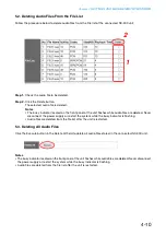
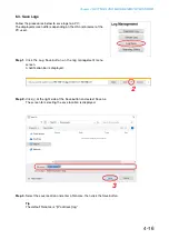
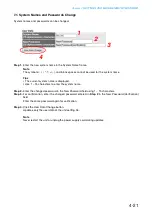
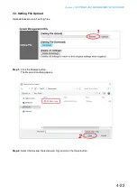
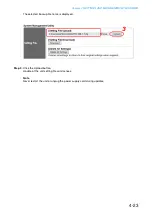
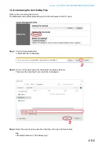
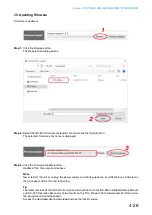
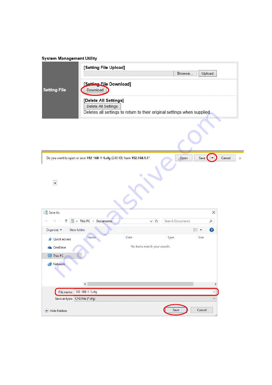
7.3. Downloading the Unit Setting Files

Back up the unit setting files to a PC.
The displayed screen differs depending on the OS and browser of the PC used.


Step 1. 

Click the Download button.
A notification bar is displayed.


Step 2. 

Click 

 at the right side of the Sa e button and select Sa e As.

The screen for selecting the sa e location is displayed.


Step 3. 

Select the sa e location and enter a  lename, then click the Sa e button.

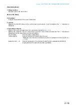
Tip

The default  lename is 

 address .cfg.

2

3

Содержание NX-300

Страница 1: ...NSTALLATION SETUP MANUAL NETWORK AUDIO ADAPTER NX 300 Than you for purchasing T s et or udio dapter lease carefully follo the instructions in this manual to ensure long trouble free use of your e uipment ...

Страница 2: ...on 2 INSTALLATION ac ounting all ounting es Top nstallation 3 BEFORE SETUP ddresses and nstallation ocations nput evel d ustment Chapter 3 SYSTEM SETTINGS NX 300 SETTING SOFTWARE 1 GENERAL DESCRIPTION inder and etting oft are bout et or ettings ac ing p etting iles autions oncerning etting pdates 2 SOFTWARE INSTALLATION ystem onditions o nloading the oft are e uired omponent nstallation etting oft...

Страница 3: ...tem diting egistered ystems eleting egistered ystems 8 SETUP EDITING SCREEN creen xplanation enu 9 SYSTEM CONFIGURATION SETTINGS mporting nit etection esults dding nits to the nit ist eleting nits from the nit ist 10 GENERAL SYSTEM SETTINGS et or ettings xternal erver ettings only roadcast pec ettings 11 PATTERN SETTINGS attern etting ummary roadcast attern ettings ontact ridge attern ettings ontr...

Страница 4: ...ver tation remises roadcasting eparture elodies ver the tation remises roadcasting eparture elodies sing the sing a icrophone to a e an mergency roadcast from the entral tation to tation during a eparture elody roadcast educing the ighttime roadcasting olume Chapter 4 SYSTEM AND MANAGEMENT BY BROWSER 1 OUTLINE OF SETTINGS USING BROWSER 2 DISPLAYING THE SETTING MENU SCREEN 3 MENU ITEMS 4 NETWORK SE...

Страница 5: ...ingle election uttons reating the roup election utton eleting reated uttons 7 PERFORMING VARIOUS OTHER SETTINGS etting the dministrator ass ord hanging the Title for the peration oft are 8 ERROR MESSAGES Chapter 6 APPENDIX 1 EXPLANATION et or and ddress et or ddress ort Translation T roadcast and nit can ulticast and imultaneous ultiple roadcasts o the ontact ridge or s aximum umber of roadcasting...

Страница 6: ...3 LEVEL DIAGRAM loc iagram evel iagram bout etting alues and udio nput evel d ustments 4 IF A FAILURE IS DETECTED 5 SPECIFICATIONS ...

Страница 7: ...Chapter 1 SYSTEM SUMMARY ...

Страница 8: ...ected The entire system can be remotely operated or managed from a single personal computer using the soft are program Operation log can be sa ed to an installed S card commercial product ecause audio transmissions can be started and nished ia the unit s contact inputs systems can be con gured e en ithout the use of a esigned to operate on either A adapter option or po er source 1 N AST A communic...

Страница 9: ... detached from the NX 300 3 Output indicator Green ights hen the le el of the signal sent out from the audio output terminal is suf cient 4 LNK ACT indicator Green ights hen the unit is connected to a net ork lashes hile the unit is transmitting or recei ing data 5 Busy indicator Green ontinuously ashes hile reading and riting data into a built in memory or S card ights for one second and then e t...

Страница 10: ... terminal 0 d for line signal le el 0 d for microphone signalle el k balanced unbalanceds itchable ecei e audio signals of microphone or line signal le el ot old arth shield 22 DIP switch for equipment settings sed hen performing audio input settings Default DIP switch setting it h Ground lift selection switch NORMAL GND LIFT A ground loop can potentially be created hen the NX 300 is connected to ...

Страница 11: ... See p 3 3 SO T A NSTA AT ON for the installation procedure 4 Operation Related Settings The NX 300 Operation rogram is re uired to make broadcasts from the The NX 300 Operation Soft are performs settings using the setting data prepared in System Setting 3 abo e Note See hapter S TT N S N SSA N S N T NX 300 O AT ON SO T A for the setting procedure 3 System Setting To perform settings use the NX 30...

Страница 12: ...Chapter 2 INSTALLATION AND CONNECTION ...

Страница 13: ...d The po er supply must ha e a capacity of o er 00 mA The range of input oltage to be fed to the po er input terminal should be between 21 6 V and 26 4 V DC If the input oltage is out of this range the unit may malfunction or fail See p emo able Terminal lug onnection for connector connection procedures AC ADAPTER DC INPUT Cord clamp AC adapter AD 246 option Note e sure the signal N terminal is se...

Страница 14: ...erminal lug onnection for audio input and output terminals connection procedures When the connected unit has an unbalanced input make the connections as follows NX 300 Connected Unit H E Hot H Cold C Earth E Shield Shield Audio output terminal connections Connect the mixer amplifier etc using 2 core shielded cable Audio input terminal connections Connect the microphone or other sound sources using...

Страница 15: ...connecting multiple units n the case of unbalanced input settings 0 d n the case of balanced input settings d When transmitting audio from one sound source to multiple channels To use the same sound source bet een channels or NX 300 units through the NX 300 s audio input terminal perform connections as sho n belo using the bridge out unction This type of connection is re uired in the follo ing cas...

Страница 16: ...INPUT CONTROL OUTPUT 1 2 3 4 5 8 C 6 7 1 2 3 4 5 8 C 6 7 ON 1 2 3 4 5 6 7 8 1 2 1 2 GND LIFT LINE PAD MIC NORMAL To other unit s control input To other unit s control input To other unit s control output Control Output 1 8 Specifications Open collector output ithstand oltage 30 ontrol current 0 mA ma imum Control Output 9 10 Specifications Relay contact output No polarity ithstand oltage 30 ontrol...

Страница 17: ...hose specified are used To ensure stable NX 300 operation it is recommended that failure detection iring be made independent from that of control input terminals 1 for hich shielded t isted pair cables shorter than 10 m 3 1 ft should be used onnect the cable s shielded ire to the NX 300 s signal N terminal 1 2 E C H AUDIO OUTPUT E C H AUDIO INPUT E C H E C H GND SIGNAL LAN AC ADAPTER DC INPUT DC I...

Страница 18: ...t ulling it out at an angle may cause the terminal plug or terminal block to break Fixing screw Terminal screw Removable terminal plug accessory Tightens Loosens 1 2 3 Slotted screwdriver Recommended type of screwdriver Blade width 1 1 For DC power input terminal About 3 5 mm 0 14 For other terminals About 2 5 mm 0 1 10 9 CONTROLINPUT 1 CONTROLOUTPUT 24V 200mA LAN ACADAPTER DCINPUT 24V 200mA DCINP...

Страница 19: ...ng screw 2 Rack mounting bracket 2 Fiber washer for M5 2 Coupler 2 5 x 12 rack mounting screw 2 M3 x 12 machine screw 2 2 INSTALLATION 2 1 Rack Mounting se the optional mounting hard are set hen installing the unit in an e uipment rack 2 1 1 When mounting a single unit se the optional 1 hard are set hen mounting a single unit 2 1 2 When mounting 2 units se the optional 1 hard are set hen mounting ...

Страница 20: ...e NX 300 YC 850 Wall mounting bracket Option Machine screw M3 x 6 supplied with the YC 850 Step 2 ount the NX 300 on the all Notes se appropriate scre s for the construction of all 3 0 ood scre s are supplied ith the 0 Wall mounting dimensions 225 5 mm 8 88 180 mm 7 09 3 5 x 20 wood screw supplied with the YC 850 ...

Страница 21: ...N AND CONNECTION 10 2 3 Desk Top Installation hen installing the NX 300 on a desk secure the supplied plastic feet to the unit s bottom using the supplied machine screws Plastic foot accessory M3 x 8 machine screw accessory ...

Страница 22: ...o and uni ue to a net orking de ice consisting of 1 hyphenated alphanumeric characters 3 2 Input Level Adjustment se the input olume control O to ad ust the audio input le el otating the ad uster clock ise as sho n in the gure increases the le el and rotating it counterclock ise decreases the le el Ad ust the le el so that the input indicator lights green and not red Note otate the input olume con...

Страница 23: ...Chapter 3 SYSTEM SETTINGS NX 300 SETTING SOFTWARE ...

Страница 24: ...differ or the screen is not displayed depending on the model explanations are provided separately on a case by case basis Items that cannot be set are displayed in gray on the screen 1 2 About Network Settings Perform settings for the NX 300 NX 100 and NX 100S units and PC networks beforehand according to the instructions of an administrator of the facility in which the unit is installed Incorrect...

Страница 25: ...ting Software the following components are required icrosoft N T rame ork or later This component need not be installed when the OS is Windows 10 Note f icrosoft N T rame ork is not pre iously installed connect the to the nternet and do nload the installer from Microsoft Corporation s download center to install it 2 SOFTWARE INSTALLATION When the NX 300 Software Collection is installed on a PC the...

Страница 26: ...d double click on the resulting setup e e le Step 2 Click the Next button The screen License Agreement will be displayed Step 3 Carefully read the contents of the License Agreement and select I Agree Then click the Next button Note Selecting I Do Not Agree followed by the Cancel button will exit the software without installing it The installer will start up 2 3 3 ...

Страница 27: ...ed folder Step 5 Click the Next button The screen ready for program installation is displayed Step 6 Click the Next button to install the software program into the selected folder The Installation Complete screen is displayed when the installation is correctly completed Step 7 Click the Close button 2 5 When NX 300 Software Uninstallation Select Control Panel Programs and Features to delete the NX...

Страница 28: ...ocation or the folder and file names Files are created inside the data folder when the settings data is saved NX 300SettingSoftware exe NX 300 Setting Software SystemSetting xml System settings file IP address cfg Unit settings file IP address cfg Unit settings file NX 300Finder exe NX 300 Finder NX 300 Setting Software Install Folder Data Folder System name NX 300SettingSoftware_Common xml Common...

Страница 29: ...connected to the LAN for the system initial setting NX 300 Setting Software sed to set up broadcasts control inputs and outputs and arious other settings of the NX 300 pload the de ice settings file created ith the NX 300 Setting Software after performing network settings using the NX 300 Finder nit settings files can also be created in ad ance by inputting the unit settings before installation Se...

Страница 30: ...work settings Manually add any units that could not be scanned and enter their IP addresses default gateways subnet masks and unit names Set the following items in the order listed eneral settings Set the items related to the entire system NX 300 only Net ork Set the unit s address and port number roadcast Spec Set the broadcast uality attern Set the destinations for the unit s broadcasts and cont...

Страница 31: ...e ontrol input and output Set unit operations hen control signals are input or output Serial Set the unit s serial bridge connection destinations NX 100 only Audio le pload the audio le to be used for broadcast to the unit NX 300 only 2 Saving Data Files Save the NX 300 Setting Software s data folder to the PC s hard disk drive or a connected external storage device Also be sure to save backup cop...

Страница 32: ...NX 300 Finder or browser Step Double click the shortcut for the NX 300 Finder which was created on the desktop when installed Or directly double click the NX 300Finder exe software created in the installed folder Tip The Select source IP address screen is only displayed when multiple IP addresses are set in the PC Select the correct source IP address and click the OK button Select source IP addres...

Страница 33: ...be used for unit detection Only units connected to the local network having the selected IP address can be detected Find units F Detects and displays all units connected to the local network pload Settings ploads the settings contents changed on the soft are screen to the unit 5 2 3 Help About A Displays the version number of the current software 5 3 Button 1 Find units button Detects and displays...

Страница 34: ...k information on the NX 300 units connected to the local network is displayed The following values are set by default address 1 1 1 1 Subnet mask 0 Default gateway 0 0 0 0 eb port 0 nit name NX 300 Notes The range that can be detected is only the range that is alid for broadcast communication from the source IP address See p 6 3 IP Broadcast and Unit Scan or the units that cannot be scanned manual...

Страница 35: ...d 2 IP address Sets the detected unit s IP address 3 Subnet mask Sets the detected unit s subnet mask 4 Default gateway Sets the detected unit s default gateway 5 Web port Sets the web server s port number 6 Model Displays the unit s model name Cannot be changed 7 Unit name Sets the name of the unit registered in the system 8 System name NX 300 only Displays the system name set in the system Unit ...

Страница 36: ...that allows the unit information list to be input Step 2 Input a new setting value into the unit information list Items that can be set are as follows address Subnet mask efault gate ay eb port nit name Step 3 Follow Steps 1 and 2 for all devices to be changed Step 4 After editing all changes click the pload settings button The new setting values are uploaded to the device Note Since the unit is a...

Страница 37: ...n be ef ciently done by reading the detection results using the NX 300 Setting Soft are See p 3 20 SETUP EDITING SCREEN Step 1 Select File Save As from the menu while the unit is displayed on the detected unit list The Save As dialog is displayed Step 2 esignate a lename and click the Sa e button The unit detection list data is saved in the XML format ...

Страница 38: ...or the NX 300 Setting Software which was created on the desktop when installed Or directly double click the NX 300SettingSoftware exe software created in the installed folder 7 OPERATION FROM THE SYSTEM EDITING SCREEN Starting the NX 300 Setting Software displays the following screen Create or edit a new system on this screen ...

Страница 39: ...m creation screen is displayed Step 2 Enter a system name and password se 1 1 characters for the system name and the pass ord Note The symbols and blank spaces cannot be used for the system name Step 3 or con rmation enter the same password entered in Step 2 in the Retype password space Step 4 Click the OK button The display is switched to the setup editing screen see p 3 20 2 3 4 ...

Страница 40: ...ng Software Step 1 Click the System selection button on the system editing screen The screen for selecting the system is displayed Step 2 From the registered system names select the system to be edited Step 3 Enter the system s password Step 4 Click the OK button The display is switched to the setup editing screen see p 3 20 2 3 4 ...

Страница 41: ... NX 300 Setting Software s data folder Click the System deletion button on the system editing screen to display the screen for selecting the existing system Select the system to be deleted and click the elete button A con rmation dialog is displayed Clicking the OK button deletes the system Select the system to be deleted ...

Страница 42: ...ng the unit to be set the current setting contents are displayed in the settings form on the right 1 System units Displays the number of units that make up the system for each model 2 General settings button sed to perform settings related to the entire system Clicking this button displays the overall setting screen See p 3 26 3 Add button Clicking this button displays the dialog for adding units ...

Страница 43: ...twork tab sed to set each unit s address and port number See p 3 28 12 Broadcast spec tab sed to set broadcast uality See p 3 35 13 Pattern tab sed to set each unit s broadcast and contact bridge destinations The Control Pattern Broadcast Pattern and Contact Bridge Pattern buttons can be used to switch between pattern setting screens See p 3 38 14 Control I O tab sed to set operations at the momen...

Страница 44: ...ord registered in the system Exit Terminates the software 8 2 2 Tool pload settings rites the setting contents to the unit Download settings Downloads the unit s setting contents to a PC pload clock settings rites the current time to the unit Options Allows access to network settings 8 2 3 Help Toa data library Starts the web browser and accesses the TOA product data download site About Displays t...

Страница 45: ...em 9 1 Importing Unit Detection Results Step 1 Click on the Import button on the setup editing screen A dialog for le selection is displayed Step 2 Select the unit selection list data XML format saved with the NX 300 Finder and click on the Open button Designated data is imported and reflected in the unit list and Network tab 2 ...

Страница 46: ... 9 2 Adding Units to the Unit List Step 1 Click the Add button on the setup editing screen A dialog for device addition is displayed Step 2 Enter the number of units to be added and click the OK button The set units are added to the unit list Unit list ...

Страница 47: ...the Unit List Step 1 Check the unit to be deleted Tip All units can be simultaneously checked using the Check all button All displayed units can be simultaneously unchecked ith the ncheck all button Step 2 Click the Delete button Checked units are deleted from the unit list 1 2 ...

Страница 48: ... the current broadcast is completed rioriti e last The current broadcast is automatically terminated allo ing the ne broadcast to go through Note hen an NX 100 or NX 100S is included in the system the priority le el is ed at rioriti e rst 2 Emergency broadcast The output sound volume can be set to increase when making a broadcast with a control pattern priority level of 1 see p 3 38 PATTERN SETTIN...

Страница 49: ...t Enter the NTP server s port number Time one Sets the unit s time one Start Sets the time to start time correction End Sets the time to end time correction 6 Summer time DST Set daylight saving time DST Enable Set whether or not to enable daylight saving time Start End Set the date and time to start and end daylight saving time esignate it in the format our of ay of nth eek of onth The last day o...

Страница 50: ...creen Step 2 Select the Net ork tab and click the nit button The network setting screen is displayed Step 3 Set each item 1 Name nter the name of the de ice p to 31 characters can be used 2 IP address Enter the IP address of the unit When the detected unit list data is imported after the IP address is set with the NX 300 Finder an assigned IP address is displayed Click ...

Страница 51: ...oted abo e nter the number from ithin the range of 1 3 efault 000 The TCP ports are assigned as follows Port Protocol Port No Default Broadcast control TCP Start port No 0 000 PC control TCP Start port No 1 001 Contact bridge TCP Start port No 2 00 Broadcast Control and Contact Bridge are used to control operations between the NX 300 and NX 100 NX 100S units se ontrol to control operations using t...

Страница 52: ... IP address Allows entry of the NX 300 s IP address as viewed from the WAN side 10 WAN TCP Port Set the start TCP port number to be used for each protocol as viewed from the WAN side Web server nter the eb ser er port number efault 0 FTP data nter the unit s T ser er data port number hich can be set ithin the range of 1 3 efault 0 FTP control nter the unit s T ser er control port number hich can b...

Страница 53: ...er of the unit s ports other than those noted abo e nter an e en number from ithin the range of 1 efault 000 The ports are assigned as follo s Port Protocol Port No Default roadcast to O T1 Start port No 0 000 roadcast to O T Start port No 2 00 Clock correction Start port No 00 Note Since port numbers 1 000 and 3 are used internally the numbers of 1 0 1 000 and 3 3 cannot be entered ...

Страница 54: ...k tab The network setting screen is displayed Step 3 Set each item 1 Name nter the name of the unit p to 31 characters can be used 2 IP address Enter the IP address of the unit When the detected unit list data is imported after the IP address is set with the NX 300 Finder an assigned IP address is displayed 3 Subnet mask Enter the subnet mask 4 Default gateway Enter the default gateway ...

Страница 55: ...ntrol TCP Start port No 0 000 PC control TCP Start port No 1 001 Contact bridge TCP Start port No 2 00 Serial bridge NX 100 only TCP Start port No 3 003 6 UDP port esignate the base port number to be used by Start port No nter the rst number of the unit s ports nter an e en number from ithin the range of 1 efault 000 The ports are assigned as follo s Port Protocol Port No Default Broadcasting Star...

Страница 56: ...to be set from the unit list on the setup editing screen Step 2 Select the Network tab and click the Others button The external server setting screen is displayed Step 3 Set each item 1 DNS server address Enter the IP address of the DNS server Default 0 0 0 0 2 DNS server port nter the port number of the NS ser er from ithin the range of 1 3 efault 3 Click ...

Страница 57: ...t from the unit list Step 2 Select the NX 300 Setting Software s Broadcast spec tab The broadcast spec setting screen is displayed Step 3 Set each item 1 Channel Settings Select the channel to be set from among hannel 1 hannel and Audio le Channel 1 Select this channel when setting broadcast specs that use Audio Input 1 and Audio Output 1 Channel 2 Select this channel when setting broadcast specs ...

Страница 58: ...he higher the number the more the sound uality is impro ed ho e er the utili ed band idth also e pands Tips annot be set hen Audio le is selected in the channel settings annot be set hen the ridge out settings are enabled cannot be selected for NX 100 or NX 100S units Reception Packet size byte Set the si e of all reception audio packets educing the packet si e e pands the band idth used ho e er d...

Страница 59: ...be registered per unit Marking the checkbox enables the sound volume control schedule function Clicking the add button displays the sound volume control schedule setting dialog Start and End Set the start time and end time for the Sound Volume Control Schedule The start and end times can be set across dates Volume dB Set the audio output level during the preset time period 1 through 20 dB or mute ...

Страница 60: ...TTINGS Selecting the Pattern tab on the setup editing screen displays the pattern setting screen Control pattern Broadcast pattern and Contact bridge pattern buttons allow switching between the Control pattern Broadcast pattern or Contact bridge pattern setting screens ...

Страница 61: ...tarting broadcasts from the NX 300 Operation Software select Broadcast Pattern 11 1 2 Pattern type and configuration ontrol roadcast and ontact ridge patterns are con gured as follo s The ontrol pattern is con gured by a combination of roadcast and ontact ridge patterns t may consist of only the Broadcast patterns or Contact Bridge patterns 11 1 3 Control pattern setting procedure Set both the Bro...

Страница 62: ...n destinations 1 locations multicast transmission connection destinations locations The number of connected destinations may drop belo 1 depending on audio speci cation settings For details see p 6 8 Maximum Number of Broadcasting Destinations 11 2 1 Broadcast pattern setting screen Clicking on the Broadcast pattern button displays the broadcast pattern setting screen Click 1 Broadcast pattern lis...

Страница 63: ...X 300 SETTING SOFTWARE 3 1 11 2 2 Creating a new broadcast pattern 1 2 Step 1 Click the Add Broadcast pattern button The ne pattern can be edited on the editing eld Step 2 Set each item See p 3 44 Broadcast pattern setting items ...

Страница 64: ...the broadcast pattern setting contents 1 2 Step 1 Select the broadcast pattern to be changed on the broadcast pattern list The change can be edited on the editing eld Step 2 Change the setting contents of the item to be changed See p 3 44 Broadcast pattern setting items ...

Страница 65: ...FTWARE 3 3 1 2 11 2 4 Deleting the broadcast pattern Step 1 Select the broadcast pattern to be deleted on the broadcast pattern list Step 2 Click the Delete Broadcast patterns button A con rmation dialog is displayed Step 3 Click the OK button 3 ...

Страница 66: ... from another unit Local Makes broadcasts from the operated unit s audio input to its audio output 4 Audio input Select the channel to be used as the input N1 N or Audio le Note Audio Files cannot be selected when Direction 3 is set to Reception Audio file selection button Only hen the Audio input is set to Audio le The audio le can be selected Number of times Only hen the Audio input is set to Au...

Страница 67: ...e o nload button The audio le list is ac uired from the unit and displayed on the pull do n list Select the lename from the pull do n list Step 3 Click the OK button 5 Audio output Select O T1 or O T for the channel to be used at the output destination 6 Connection destination A list of units to be used for broadcast The names of the internal units that make up the system are displayed To select c...

Страница 68: ... in a contact bridge pattern 11 3 1 Contact bridge pattern setting screen Clicking the Contact bridge pattern button displays the setting screen 1 Contact bridge pattern list The list of registered contact bridge patterns is displayed p to 0 patterns can be set per unit 2 Add contact bridge pattern button sed to add ne contact bridge patterns 3 Delete contact bridge pattern button sed to delete re...

Страница 69: ...SETTING SOFTWARE 3 11 3 2 Creating a new contact bridge pattern Step 1 Click the Add contact bridge pattern button The ne pattern can be edited on the editing eld Step 2 Set each item See p 3 50 Contact bridge pattern setting items 1 2 ...

Страница 70: ...t bridge pattern setting contents 1 2 Step 1 Select the contact bridge pattern to be changed on the Contact Bridge Pattern list The change can be edited on the editing eld Step 2 Change the setting contents of the item to be changed See p 3 50 Contact bridge pattern setting items ...

Страница 71: ...11 3 4 Deleting the contact bridge pattern 1 2 Step 1 Select the contact bridge pattern to be deleted on the Contact Bridge Pattern list Step 2 Click the Delete contact bridge pattern button A con rmation dialog is displayed Step 3 Click the OK button 3 ...

Страница 72: ...et the unit s control output number to be activated se the units sho n on the unit list to e ecute the contact bridge The list of unit names that constitute the system and the control output numbers are displayed To select a control output number mark the control output number checkbox located at the right side of the unit name indication The total number of selected units is displayed at the righ...

Страница 73: ...rce 1 le transmission or Audio Source 1 le transmission Audio Source le transmission Audio Source 3 le transmission Only one broadcast pattern reception and local can be set for Output 1 and Output respecti ely 11 4 1 Control pattern setting screen Clicking the Control pattern button displays the control pattern setting screen 1 Control pattern list Displays the list of registered control patterns...

Страница 74: ...GS NX 300 SETTING SOFTWARE 3 11 4 2 Creating a new control pattern 1 2 Step 1 Click the Add control pattern button The ne pattern can be edited on the editing eld Step 2 Set each item See p 3 55 Control pattern setting items ...

Страница 75: ...ging the control pattern setting contents Step 1 Select the control pattern to be changed on the control pattern list The change can be edited on the editing eld Step 2 Change the setting contents of the item to be changed See p 3 55 Control pattern setting items 1 2 ...

Страница 76: ...NG SOFTWARE 3 11 4 4 Deleting the control pattern Step 1 Select the control pattern to be deleted on the control pattern list Step 2 Click the Delete Control patterns button A con rmation dialog is displayed Step 3 Click the OK button 3 1 2 ...

Страница 77: ...oadcast pattern The list of broadcast patterns set on the broadcast pattern setting screen is displayed Mark the checkbox of the broadcast pattern to use Bandwidth Displays the bandwidth to be used for the selected broadcast pattern Note hen a broadcast pattern that uses an audio le is included in the selected broadcast pattern the bandwidth is not displayed 5 Contact bridge pattern Select from th...

Страница 78: ... click on the Control input button The control input setting screen is displayed Step 3 Set each item 1 Control input No Click the control input number to be set 2 Enable Marking this checkbox validates the item settings for the control input 3 Enable surveillance This function can only be set for ontrol nput hen Sur eillance is enabled in the eneral Settings Marking the checkbox allows Surveillan...

Страница 79: ... the broadcast does not stop until it has completed its designated number of repetitions even if the control input is turned OFF hen multiple control inputs are simultaneously set to ON each control pattern is started at 0 ms intervals f the start of the control pattern is interrupted the broadcast ill be uickly terminated at the recei ing end When the chattering time is set to Long its duration i...

Страница 80: ...Software Step 1 Select the units to set from the unit list on the setup editing screen Step 2 Select the Control I O tab and click on the Control input button The control input setting screen is displayed Step 3 Set each item 1 Control input No Click the control input number to be set 2 Enable Marking this checkbox validates the item settings for the control input Click ...

Страница 81: ...egarded as ON 5 Broadcast pattern Designate the broadcast pattern to be activated when the control input is turned ON The maximum number of connection destinations is as follows eception 1 location unicast transmission locations multicast transmission locations Note Broadcasts to multiple transmission destinations two way broadcasts and local broadcasts may not be made depending on the broadcast s...

Страница 82: ...e unit list The list of unit names and control output numbers that constitute the system is displayed To select mark the desired control output number checkbox located on the right of the unit name indication The total number of selected units is displayed at the right of the Number of units indicator Note NX 100 and NX 100S units cannot be used to control NX 300 unit control outputs 9 and 10 ...

Страница 83: ...be checked by default When the control output is not used uncheck the checkbox to invalidate the control output settings 3 Mode Select the operation mode Contents differ depending on the unit being set For the NX 300 units Standard Standard operation mode Control output is activated by the PC or contact bridge control of an operated unit or other unit Broadcasting Control output is activated durin...

Страница 84: ...be set f setting an NX 300 unit ontrol Output is ed to omentary f setting an NX 100 100S unit Momentary Provides output during the period between reception of a start request till reception of a stop request Latch Provides output for a period of 1 second after a start request or stop request is received Note The unit may not function correctly if operations from start to stop are completed within ...

Страница 85: ...p 3 Set each item 1 Enable Mark the checkbox to allow input of each item 2 Protocol Select the serial bridge communication method TCP server The unit selected on the setting screen functions as a TCP server and carries out communications TCP client The unit selected on the setting screen functions as a TCP client and carries out communications Clicking the radio button permits selection of the con...

Страница 86: ... communication The connected unit is not disconnected if the timeout duration is set to 0 Valid only when TCP Server or TCP Client is selected in the protocol settings 10 Transmit Receive raw data Tick the checkbo hen transmitting and recei ing ra data ata ith control information to be utili ed between NX 100 units is usually transmitted but raw data communications are generally carried out ithout...

Страница 87: ...ations are in progress hen the codec is Sub and A or hen setting the number of audio le play repetitions 1 10 insert silence inter als at both the beginning and end of the audio le Tip Audio le upload and deletion can also be set using the bro ser For details please see p 4 7 AUDIO FILE MANAGEMENT 15 1 Uploading Audio Files Step 1 Select the unit to be set from the unit list on the setup editing s...

Страница 88: ...M SETTINGS NX 300 SETTING SOFTWARE 3 Step 4 Select the audio le and click the Open button The list of audio les to be uploaded is displayed Step 5 lick the pload button The audio le is uploaded to the NX 300 unit 4 5 ...

Страница 89: ...g screen Step 2 Select the Audio ile tab and click the elete audio le button The delete audio les screen is displayed An error dialog is displayed if the PC cannot be connected to the unit Step 3 lick the audio le to be deleted and click the elete button The audio le is deleted Also clicking multiple audio les allo s the les to be selected to delete ...

Страница 90: ...Changing the System Name and Password The current system name can be changed by assigning another name and saving it Passwords can also be changed Step 1 Select File Save As from the menu A dialog for saving the system is displayed Step 2 Enter a system name and password se 1 1 characters for the system name and the pass ord Note The symbols and blank spaces cannot be used for the system name Step...

Страница 91: ...rd from the menu A dialog for changing the password is displayed Step 2 Enter the old password and a new password Set the pass ord using 1 1 characters Step 3 or con rmation enter the ne pass ord entered in Step 2 in the Retype new password space Step 4 Click the OK button Step 5 Select File Save from the menu The de ice le ith the changed pass ord is sa ed 2 3 4 ...

Страница 92: ...e unit setting le is sa ed Step 2 Select Tool pload settings from the menu A dialog for selecting the units to be uploaded is displayed Step 3 Select the unit to be uploaded from the unit list and click the OK button Note nit setting le upload takes some time Take care to ne er s itch off the NX 300 NX 100 or NX 100S po er during the upload The unit is automatically restarted after upload completi...

Страница 93: ...the OK button After download the results of a comparison of the new unit settings with those retained by the NX 300 Setting Software are shown If both settings match the No differences indicator is displayed If they do not match the Differences exist indictor is displayed Step 3 Check the contents and click the OK button Settings downloaded from the unit are reflected in the NX 300 Setting Softwar...

Страница 94: ...isplayed Step 2 ncheck the nable to change net ork settings bo Step 3 Click the OK button The option screen is closed lick on the Net ork tab to con rm that the net ork settings are disabled Tip To re edit network settings check Enable to change network settings on the option screen 16 8 Accessing the TOA Product Data Download Site To access the TOA product data do nload site select elp TOA data l...

Страница 95: ... oltage signal hile the switch is held down Three switches are required to execute all application examples shown in this section PC Install the NX 300 Finder NX 300 Setting Software and NX 300 Operation Software in advance See p 3 3 SOFTWARE INSTALLATION Stations A B and C NX 300 Ampli er se ampli ers that can be acti ated ith a no oltage control signal urther connect the unit s Audio Output 1 to...

Страница 96: ...ING THE NX 300 FINDER Step 2 Start the NX 300 Setting Software with the central station s PC and set the broadcast patterns for the NX 300 unit installed at the central station as follows Application Example 1 ake microphone announcements from the central station to Station A premises by actuating the ampli er with a make contact from the switch box Pattern name Mic Broadcast to Station A Directio...

Страница 97: ...rns for the NX 300 unit installed at the central station using the NX 300 Setting Software as follows Pattern name Activation of Station A s Amp Contact bridge Name NX 300 unit name of station A Control output No Number of NX 300 s control output terminal which station A s ampli er is connected to ...

Страница 98: ...ep 2 set control patterns for the NX 300 unit installed at the central station using the NX 300 Setting Software as follows Pattern name Announcement to Station A Priority Broadcast pattern Mic Broadcast to Station A Contact bridge pattern Activation of Station A s Amp ...

Страница 99: ...A Step 6 pload all settings to each unit For the upload procedure see p 3 70 Uploading Unit Setting Files 17 2 2 Operating procedure and device operation Step 1 old do n S itch 1 on the central station s s itch bo The control output terminal of Station A s NX 300 unit is closed actuating Station A s ampli er ith a make contact Step 2 Make the announcement using the central station s microphone whi...

Страница 100: ...NX 300 Setting Soft are s audio le upload procedure see p 3 65 AUDIO FILE SETTINGS or the bro ser connection s audio le upload procedure see p 4 7 AUDIO FILE MANAGEMENT Step 3 Start the NX 300 Setting Software with the central station s PC and set the broadcast patterns for the NX 300 unit installed at the central station as follows Application Example 2 roadcast a departure melody from the centra...

Страница 101: ...rns for the NX 300 unit installed at the central station using the NX 300 Setting Software as follows Pattern name Activation of Station B s Amp Contact bridge Name NX 300 unit name of station B Control output No Number of NX 300 s control output terminal which station B s ampli er is connected to ...

Страница 102: ...3 set control patterns for the NX 300 unit installed at the central station using the NX 300 Setting Software as follows Pattern name Departure Melody to Station B Priority Broadcast pattern Melody Broadcast to Station B Contact bridge pattern Activation of Station B s Amp ...

Страница 103: ...d Control pattern Departure Melody to Station B Step 7 pload all settings to each unit For the upload procedure see p 3 70 Uploading Unit Setting Files 17 3 2 Operating Procedure and Unit Operation Step 1 old do n S itch on the central station s s itch bo The control output terminal of Station s NX 300 unit is closed actuating Station s ampli er ith a make contact The departure melody is broadcast...

Страница 104: ...Soft are s audio le upload procedure see p 3 65 AUDIO FILE SETTINGS or the bro ser connection s audio le upload procedure see p 4 7 AUDIO FILE MANAGEMENT Step 3 Start the NX 300 Setting Software with the central station s PC and set the broadcast patterns for the NX 300 unit installed at the central station as follows Application Example 3 Broadcast the departure melody from the central station to...

Страница 105: ... 5 Start the NX 300 Operation Software with the central station s PC and set the Individual Selection buttons for the NX 300 unit installed at the central station as follows Display name Departure Melody to Station C Broadcast pattern Melody Broadcast to Station C Control output No Number of NX 300 s control output terminal hich station s ampli er is connected to ...

Страница 106: ...rating procedure and unit operation Step sing the NX 300 Operation Soft are click on the eparture elody to Station button Station C s NX 300 control output terminal 1 is closed Station s ampli er is actuated ith a make contact and the departure melody is broadcast ...

Страница 107: ... NX 300 Setting Soft are set the broadcast patterns as follo s for the NX 300 unit installed at the central station Application Example 4 ith the NX 300 Operation Soft are actuate the ampli er ith a make contact and using a microphone make the Emergency Broadcast from the central station to Station C during the departure melody broadcast Pattern name Emerg Broadcast to Station C Direction Transmis...

Страница 108: ...p 2 set control patterns for the NX 300 unit installed at the station C using the NX 300 Setting Software as follows Pattern name Emergency Alert to Station C Priority 1 Broadcast pattern Emerg Broadcast to Station C Contact bridge pattern Activation of Station C s Amp ...

Страница 109: ...t installed at the central station using the NX 300 Setting Software as follows Control input No 3 Enable Disable Enable Type Momentary Polarity Make Chattering time Standard Control pattern Emergency Alert to Station C Step 5 pload all settings to each unit For the upload procedure see p 3 70 Uploading Unit Setting Files ...

Страница 110: ...inal 1 is closed Station s ampli er is actuated ith a make contact and the departure melody is broadcast Step 2 When an Emergency Broadcast is required continue to press Switch 3 The departure melody broadcast is terminated Step 3 Make announcements at the central station s microphone while holding down Switch 3 The announcements are broadcast over Station C Step 4 Release Switch 3 The microphone ...

Страница 111: ...0 unit installed at each station For setting procedures see p 3 10 STARTING THE NX 300 FINDER Step 2 sing the NX 300 Setting Soft are set the olume control schedule as follo s for the NX 300 unit installed at each station Application Example 5 Station premise broadcasts at Stations A and are made at a lo er olume at night 11 00 00 A than during daytime hours Enable ON Start our 3 Minute 00 End our...

Страница 112: ...ch unit For the upload procedure see p 3 70 Uploading Unit Setting Files 17 6 2 Unit operation At each station the daily broadcast olume bet een the hours of 11 00 and 00 A is d lo er than during daytime hours Tip After setting completion no further operations are required for each unit ...

Страница 113: ...Chapter 4 SETTINGS AND MANAGEMENT BY BROWSER ...

Страница 114: ...k settings add the units manually using a PC installed with the NX 300 Setting Software then perform the required settings See p 3 8 SETTING PROCEDURE There may be cases in hich an address is duplicated or the and NX 300 unit are set up to be connected to different networks When performing network settings using a browser connect only one 1 NX 300 unit within the same network or isolate from the n...

Страница 115: ... hen the eb ser er port number is 0 the 0 description can be omitted as follo s The user authentication screen appears Note This screen will look slightly different depending on the browser being used Example http address eb ser er port number http 192 168 1 1 Step 2 Enter the user name and the password then press the OK button Notes or the user name enter the system name set for the NX 300 unit t...

Страница 116: ...t See p 4 7 og anagement See p 4 11 System Management See p 4 19 Menu Change the connected NX 300 unit s IP address subnet mask and default gateway Audio files stored in the connected NX 300 unit are displayed Audio files can also be added or deleted Operation logs and stream logs can be browsed and sa ed and the current operating status can also be browsed Change passwords or upload and download ...

Страница 117: ...er er control port number efault 1 Inter unit control Enter the control port number between NX 300 units Default 35285 Start port No nter the rst number of the unit s T port other than the eb ser er T and inter unit control Default 5000 Type and Port No A list of port types and numbers used for controlling NX 100 100S units and the NX 300 Operation Software is displayed The TCP ports are assigned ...

Страница 118: ...Default roadcast to O T1 Start port No 0 5000 roadcast to O T Start port No 5002 Clock correction Start port No 00 5 Save button Writes settings to the connected NX 300 unit s internal unit setting file Notes Changed network settings are not immediately updated The unit s settings change to the new setting contents upon restart Restart the unit by pressing the restart button that appears at the up...

Страница 119: ... Delete button File Name Displays the filename fs kHz Displays the sampling frequency of the audio file Codec Displays the compression format of the audio file Size KB Displays the size of the audio file Playback Time Displays the length second of the audio file 3 Delete All To delete all audio files registered in the connected NX 300 unit click the Execute button 5 AUDIO FILE MANAGEMENT lick Audi...

Страница 120: ...llow the procedure below to add audio files to the connected NX 300 Step 1 Click the Browse button The file selection dialog opens 2 3 Step 2 Select the audio le e tension a and click the Open button The selected audio file s filename is displayed Step 3 Click the Add button ...

Страница 121: ...ions for adding an audio le are as follo s File Format WAV Sampling Frequencies 8 16 32 48 kHz Codec PCM Sub band ADPCM Maximum No of Stored Files 8 Maximum Storage Capacity 1 MB per audio file Quantization Bit No 16 bits Channel Number Monaural hen the codec is Sub and A or hen setting the number of audio le play repetitions 1 10 insert silence inter als at both the beginning and end of the audio...

Страница 122: ...audio les are deleted Ne er disconnect the po er supply or restart the system hile the busy indicator is ashing Audio les are deleted from the le list after the unit is restarted 1 2 5 3 Deleting All Audio Files Click the Execute button in the Delete All field to delete all audio files stored in the connected NX 300 unit Notes The busy indicator located on the front panel of the unit ashes hile au...

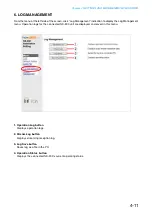
Страница 123: ... to display the og anagement menu Operation logs for the connected NX 300 unit are displayed and sa ed in this menu 1 Operation Log button Displays operation logs 2 Stream Log button Displays streaming reception log 3 Log Save button Sa es log as a le in the 4 Operation Status button Displays the connected NX 300 s current operating status ...

Страница 124: ...og management menu screen displays the operation log screen Operation logs are displayed o er multiple pages Operation button 1 Latest button pdates the operation log to current data 2 Prev Page button o es to the pre ious page 3 Next Page button o es to the ne t page 4 Clear button Deletes all operation logs ...

Страница 125: ...EM System information STREAM Status of audio stream O Time correction 7 Requesting Source ndicates the addresses of communication parties or re uesting sources of the e ents such as designating control inputs 8 Contents ndicates the contents of e ents The contents of the caution le el are displayed in yello and errors are displayed in red Tip Displaying the operation log page of the unit that has ...

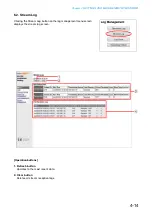
Страница 126: ... BROWSER 4 14 Operation buttons 1 Refresh button pdates to the most recent data 2 Clear button Deletes all stream reception logs 6 2 Stream Log licking the Stream og button on the log management menu screen displays the stream log screen ...

Страница 127: ...ream transmission source oss eco ery isplays the correction method at the time a missing packet is detected orrect eception Sho s the number of correctly recei ed packets the number of error packets and reco ered packets is not included oss isplays the number of unreco ered packets out of those lost due to net ork failure Silent Tone Insertion Displays the number of packets reproduced without soun...

Страница 128: ...rowser of the PC used Step 1 lick the og Sa e button on the log management menu screen A notification bar is displayed Step 2 Click at the right side of the Sa e button and select Sa e As The screen for selecting the sa e location is displayed Step 3 Select the sa e location and enter a lename then click the Sa e button Tip The default lename is address log 2 3 ...

Страница 129: ...Chapter 4 SETTINGS AND MANAGEMENT BY BROWSER 1 6 4 Operating Status Clicking the Operating Status button on the log management menu screen displays the operating status screen ...

Страница 130: ...ays the results of inspection of the sur eillance function see p 3 27 isplays the indication O for normal status and N hen a failure is detected The indication is displayed hen the sur eillance function is disabled o er Supply etects po er oltage drop Control input 8 Detects failure of the Control Input 8 circuit Displayed when the failure detection function is enabled for Control Input 8 see p 3 ...

Страница 131: ...TTINGS AND MANAGEMENT BY BROWSER 4 19 7 SYSTEM MANAGEMENT Unit Data 1 Unit Name Enter the name of the unit using up to 31 characters 2 Unit Data Change button pdates only the unit information of the unit setting le ...

Страница 132: ...to a PC 8 Delete All Settings Deletes all settings to return them to their original settings when supplied The unit is factory preset as follows IP Address 192 168 1 1 nit Name NX 300 System Name NX 300 Password guest Note To ie other settings use the bro ser or connect ith the NX 300 Setting Soft are 9 Firmware Update pdates rm are 10 Clock Setting Set the NX 300 unit s clock 11 Unit Restart Clic...

Страница 133: ...nt system name is displayed se 1 1 characters to enter the system name Step 2 Enter the changed password in the New Password field using 1 15 characters Step 3 For confirmation enter the changed password entered in Step 2 in the New Password Verification field nter the same pass ord again for eri cation Step 4 lick the ser ata hange button pdates only the user data of the unit setting le Note Ne e...

Страница 134: ...D MANAGEMENT BY BROWSER 4 22 7 2 Setting File Upload ploads backed up unit setting les Step 1 Click the Browse button The file selection dialog opens Step 2 Select the backup file extension cfg and click the Open button 1 2 ...

Страница 135: ... AND MANAGEMENT BY BROWSER 4 23 The selected backup file name is displayed Step 3 lick the pload button pdate of the unit setting le commences Note Ne er restart the unit or unplug the po er supply cord during updates 3 ...

Страница 136: ... depending on the OS and browser of the PC used Step 1 Click the Download button A notification bar is displayed Step 2 Click at the right side of the Sa e button and select Sa e As The screen for selecting the sa e location is displayed Step 3 Select the sa e location and enter a lename then click the Sa e button Tip The default lename is address cfg 2 3 ...

Страница 137: ...em to their default settings Step Click the Delete All Settings button All settings are deleted returning them to their default settings The unit is factory preset as follows IP Address 192 168 1 1 nit Name NX 300 System Name NX 300 Password guest To ie other settings use the bro ser or connect ith the NX 300 Setting Soft are ...

Страница 138: ...ick the irm are pdate button pdate of the irm are commences Note Ne er restart the unit or unplug the po er supply cord during updates or hile the busy indicator on the front panel of the this unit is ashing Tip The latest ersions of the NX 300 rm are and instruction manuals NX 300 nstallation Setup anual and NX 300 Operation Manual can be found on the TOA Product Data Download site http www toa p...

Страница 139: ...n The unit s clock is updated to the acquired time 7 7 Reflecting Changed Settings Unit Restart licking the nit estart button restarts the unit e sure to restart any time the setting contents are changed Step Click the Unit Restart button The unit restarts re ecting the contents changed after it as started Notes Ne er restart the unit or unplug the po er supply cord during updates or hile the busy...

Страница 140: ...Chapter 5 SETTINGS NECESSARY WHEN USING THE NX 300 OPERATION SOFTWARE ...

Страница 141: ...rning broadcast pattern settings see p 3 40 Broadcast Pattern Settings 2 Controls the NX 300 s control outputs by way of the network Control output can be controlled for up to 500 units 10 control output channels per button 2 STARTUP AND INITIAL SCREEN Step 1 Either double click on the NX 300 Operation Software shortcut created on the desktop during installation see p 3 4 or double click on the NX...

Страница 142: ...Chapter 5 SETTINGS NECESSARY WHEN USING THE NX 300 OPERATION SOFTWARE 5 3 The following screen is displayed during initialized status when nothing has yet been set after system selection ...

Страница 143: ...t to be activated The maximum number of buttons that can be registered is 3200 One broadcast pattern or up to 500 units X 10 control output channels can be set per Selection button 3 Streaming option Broadcast priority can be selected If the Emergency button is selected priority level 1 is assigned to the broadcast Tip Setting the emergency broadcast setting to ON using the NX 300 Setting Software...

Страница 144: ...n 1 Unit list Displays the status of managed units Double clicking a line on the list displays detailed information Right click menu Right clicking the line on the list displays the following menu Display details Displays detailed unit information See p 5 8 Detail Screen Browser connection Starts up the browser and displays the device setting screen ...

Страница 145: ...s 3 STATUS Displays unit status Standby Indicates that unit is in standby mode Broadcasting Indicates that unit is being used for broadcast Connection failure Indicates that unit is in a state of being incapable of communication 4 C_IN 1 8 C_OUT 1 10 Displays the status of control inputs and outputs ...

Страница 146: ...ays PC network information Connection destination network Displays the network interface card in use System communication setting Indicates that the PC is operating on IPv4 IPv4 address Displays the PC s IPv4 address 3 3 Status Screen Clicking the Status tab displays the status screen showing the NX 300 Operation Software s operating status ...

Страница 147: ... 1 NAME Displays the unit name 2 Model Displays the model name 3 IP address Displays the IP address 4 State Displays the current status such as Broadcasting or Standby 5 Update button Updates the displayed content of the detail screen to the latest conditions 6 Browser connection button Starts up the browser and accesses the unit 7 Close button Closes the detail screen ...

Страница 148: ...RY WHEN USING THE NX 300 OPERATION SOFTWARE 5 9 Broadcast destination tab When the unit is broadcasting the list of all destinations the unit is broadcasting to is displayed Control I O tab Displays unit input and output status ...

Страница 149: ... button size Changes the size of the single selection button Group selection button size Changes the size of the group selection button Operation log Displays the operation log screen 4 1 3 Tool Setting tool Displays the setup tool screen Button setting Creates or edits the single and group selection buttons 4 1 4 Help About Displays the NX 300 Operation Software s version information ...

Страница 150: ...ting destinations to be actuated by the NX 300 Operation Software must be set as Broadcast Pattern for the system s NX 300 NX 100 and NX 100S units 5 SETTING PROCEDURES USING THE NX 300 OPERATION SOFTWARE 1 Set the Button Set the Selection buttons that select the broadcast patterns or control outputs to be activated 2 Set the Button layout Edit the layout of the single and group selection buttons ...

Страница 151: ...ons for selecting broadcasting destinations and the group selection button 6 1 Creating Single Selection Buttons Create buttons to select broadcast patterns and control outputs Step 1 Select Tool Button setting from the menu bar The button setting screen and pallet are displayed Button setting screen Button setting pallet ...

Страница 152: ...pallet 3 Step 3 Select the position of the button on the button setting screen To select click the grid where the button is to be located in the single selection button location area Step 4 Select the color of the button Clicking the desired button color on the button setting pallet causes the clicked color to appear floating in the display ...

Страница 153: ...t a time can be selected To clear the setting contents of the selected NX 300 NX 100 and NX 100S broadcast pattern click the leftmost Clear button in the Edit area Step 8 Check the control output to be activated in the Control output list The channel number of the control output can be selected Step 9 Check the channel number of the control output To clear the setting contents of all NX 300 NX 100...

Страница 154: ...Group Selection button is used to simultaneously select multiple Single Selection buttons Register the Single Selection buttons to be controlled by the Group Selection button Step 1 Select Tool Button setting from the menu bar The button setting screen and pallet are displayed Button setting screen Button setting pallet ...

Страница 155: ...ON SOFTWARE 5 16 2 Step 2 Select the Group selection tab on the button setting pallet 3 Step 3 Select the position of the button on the button setting screen To select click the grid where the button is to be located in the group selection button location area ...

Страница 156: ...age of the button is displayed on the grid of the button setting screen Step 6 Enter the display name in the editing field of the button setting pallet Step 7 Check the Single Selection buttons to be simultaneously selected on the registered button list Step 8 Repeat Steps 2 7 as often as required Step 9 Click the Completion button on the button setting pallet Both the button setting screen and bu...

Страница 157: ... of button to be deleted on the button setting pallet Select the Single Selection tab to delete Single Selection buttons and the Group Selection tab to delete Group Selection buttons Step 2 Select the button to be deleted on the button setting screen To select click the grid where the button to be deleted is located If the button is located on the grid the Delete button in the button selection pal...

Страница 158: ... the Delete button on the button setting pallet The button selected on the button setting screen is deleted Step 4 Click the Completion button on the button setting pallet Both the button setting screen and pallet are closed and the designated button is deleted from the button screen 3 4 ...

Страница 159: ...tions of settings can be prevented Once the password has been set the user authentication screen shown at right is displayed when attempting to operate the Setting Tool and Button Settings When the user authentication screen is displayed enter the correct password and click the OK button Step 1 Select Tool Setting tool from the menu bar The setting tool screen is displayed 2 3 Step 2 Select the ty...

Страница 160: ...new password using up to 15 characters Tip Password settings can be reset if a change is made with the New Password field left blank Step 5 For confirmation enter the new password entered in Step 4 in the Confirm new password field Step 6 Click the Change button The confirmation screen is displayed Step 7 Click the Yes button on the confirmation screen The new password is set ...

Страница 161: ...in the title bar and task bar can be changed Step 1 Select Tool Setting tool from the menu bar The setting tool screen is displayed 4 3 2 Step 2 Click the Software tab The software screen is displayed Step 3 Enter the title to be set in the title setting field Default NX 300 Operation Software Step 4 Click the OK button The setting tool screen is closed and the title is changed ...

Страница 162: ...read unit list Confirm the unit list file System information not found Create unit list then restart Create system settings using the NX 300 Setting Software thenrestarttheNX 300OperationSoftware Failed to save edited data Terminate the NX 300 Operation Software and restart then save again Broadcast failed Terminate operation and try again later Terminate broadcast and control output during activa...

Страница 163: ...Chapter 6 APPENDIX ...

Страница 164: ...address This is the only address that is used to access the Internet To use the unit through the nternet fixed global addresses must be acquired and assigned to it or the router if it is used hen a connection is made from nit to nit in the figure the local address can be used o ever hen a connection is made from Unit C to Unit A the global IP address must be used The fixed global address must be a...

Страница 165: ... 255 255 255 IP broadcast does not reach beyond the router covering range even in the LAN NET1 NET2 Router Router NX 300 C NX 300 A NX 300 B PC n the above figure T represents the and T represents the effective range for broadcast or example if the is used to scan the units in the figure nit cannot be scanned even though it is located within the same LAN Note Consult a network administrator about ...

Страница 166: ...two or more units The advantage of multicast operation is the possibility of decreasing traffic et or s that use multicast communication need to be supported by multicast addresses and Internet Group Management Protocol IGMP The effective multicast address range is from 224 0 0 0 to 239 255 255 255 Note Consult a network administrator when performing settings ...

Страница 167: ...ontact bridge control is detected the system automatically attempts to reestablish control after a 5 second interval retry operation The retry operation continues until the contact bridge has been successfully controlled or the control input status has changed Control input Control output Network communication Input ON 5 s Output ON ON Control result NG ON Control result NG 5 s ON Control result O...

Страница 168: ...lo hen the control input or output device s po er is s itched or Control output ON Power ON Power ON Control input device Control output device Control input ON Network Operations caused by a change in the control input device s power status Control input device Control input ON ON Control output ON ON Control output device ON ON Power OFF Power ON Network Transmits initial status information when...

Страница 169: ...used by a change in the control input and output devices power statuses Control input device Control output device Control output device Control input device 1 ON 1 ON 1 ON 2 ON 2 ON hile a contact bridge signal is being received from the first entered control input if another contact bridge signal is received from control input the control bridge is terminated allo ing the last control bridge to ...

Страница 170: ...t When another broadcast with a priority higher than that of the current broadcast is made the broadcast with the lower priority is interrupted allowing the last high priority broadcast to go through hen another broadcast ith the same priority level as that of the current broadcast is made if mode is selected in the Same Priority Broadcast settings the current broadcast is interrupted and the last...

Страница 171: ...pleted xample Tip Use the NX 300 Setting Software to perform the same priority broadcast settings See p 3 26 GENERAL SYSTEM SETTINGS Notes riority levels set using the etting oft are are only valid for broadcasts ith units on the receiving side roadcasts ith units on the receiving side in systems in hich both and units are used are al ays performed on a basis regardless of priority settings f both...

Страница 172: ...the s input settings ta e care hen connecting multiple units hen the input is set to and unbalanced input d hen the input is set to and balanced input d hen the input is set to and unbalanced input d Tips p to channels of se uential audio source transmission are possible The etting oft are is necessary to enable this function See p 3 35 Broadcast Spec Settings Distributing an audio source using th...

Страница 173: ...s log se a to confirm the contents of the ac uired operation logs 1 9 2 About the usable SD cards eparately prepare the card to be used ards ith capacities of up to can be used either mini cards nor micro cards can be used The is not compatible ith cards hen using cards of up to use T formatted cards hen using cards of up to use T formatted cards When formatting with a PC be sure to use only the d...

Страница 174: ...icity could cause irreparable damage Step 1 emove the unit s top panel Step 2 Cut jumper SJP203 on the circuit board using a pair of nippers Step 3 Replace the top panel NE TW OR KAU DIOAD AP TE R NX 300 ST AT US BU SY RU N ER RO R SD CA RD RE SE T OU TP UT INPU T LN K AC T VO LU ME 2 1 2 1 2 1 NX 300 Circuit board Top panel SJP203 Cut Jumper SJP203 Front panel side SJP203 eave the or described he...

Страница 175: ...unit s top panel Step 2 Change jumper positions on the circuit board indicates the umper positions in the figures belo or hannel move the umpers ithin roup and for hannel move the umpers ithin roup closer to the front panel Step 3 Replace the top panel NE TW OR KAU DIOAD AP TE R NX 300 ST AT US BU SY RU N ER RO R SD CA RD RE SE T OU TP UT INPU T LN K AC T VO LU ME 2 1 2 1 2 1 NX 300 Top panel Circ...

Страница 176: ...rror on for s then off 7 Run indicator Green irm are malfunction irm are normal operation Normal indicator status INPUT OUTPUT 2 ACT 3 BUSY 4 STATUS 5 ERROR 6 RUN 7 Description Starting up for 30 seconds or or or or Continues for 30 seconds after the unit is turned on If this status remains unchanged over 30 seconds this shows unit failure Contact your TOA dealer No audio signals input and output ...

Страница 177: ... setting errors Establish a connection to the unit to be controlled Network disconnection LAN cable is disconnected or network equipment is turned off Ensure each connection to the network equipment ailure detection Check power supply and control inputs and ensure they are all correctly connected pload audio files correctly No audio signal input If this happens though the Audio input terminal is c...

Страница 178: ...used as an input volume control default setting When used as an output volume control PAD settings MIC LINE settings Gain settings Imaginary amplifier Signal level dB 6 dB signal input 20 dB signal input 45 dB signal input 60 dB signal input 22 dB signal input 20 10 0 10 20 30 40 50 60 LPF Maximum input level 0 dB 1 V Output level when bridge out function is set Tips Volume control is set to maxim...

Страница 179: ...evel by default but can be changed to the output volume control by changing jumper settings see p Even if changed to the output volume control the audio input setting values and output values remain the same as shown above f umper settings are changed the audio output levels provided by the can be ad usted ith the input level control hen the audio output to a connected amplifier is too high ad ust...

Страница 180: ... that unit s address subnet mas and default gate ay are correctly set See p etecting nits or p 3 28 Network Settings for network setting procedures hen connected to other net or s via router confirm ith net or management personnel if the router is properly set Browser setting screen is not properly displayed hec using bro ser for correct connection lso confirm that browser is correctly set etting ...

Страница 181: ...tput is affected by noise or lost When hum noise is heard unit s SIGNAL GND terminal may not be correctly connected Check to see if it is correctly connected When short noises are heard or when audio output is lost network may be congested Check log contents If congestion is found consult with network management personnel ee p tream og to confirm log contents udio outputs are mixed hen broadcasts ...

Страница 182: ...ut ailure etection Section onnection resistance to ma e the function inactive onnection resistance to ma e the function active Connector cable Twisted pair cable Shielded type is recommended aximum cable distance m Control Output 8 channels open collector output polarized withstand voltage 30 V DC control current m max removable terminal bloc pins 2 channels relay output non polar withstand voltag...

Страница 183: ...ting bracket YC 850 AC adapter AD 246 d 2 Not compatible with SDXC memory cards SD Section or log storage ax edia card ax 2 ile system T T se only memory cards rated at m current consumption or less o card provided Installation Method Rack Desk Surface mount Operating Temperature to to to or to hen adapter is in use perating umidity or less no condensation inish Pre coated steel plate black 30 glo...

Отзывы: