Chapter 2
INSTALLATION AND CONNECTION
-
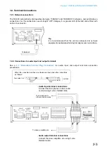
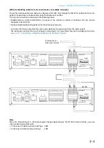
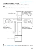
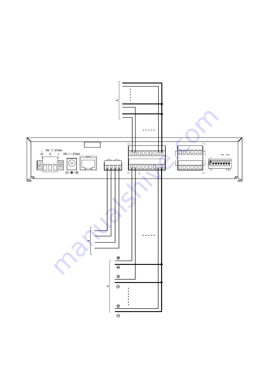
1.2.3. Connections to control input and output terminals
onnect the control input and output terminals of all other connected units using control lines.
Note
e sure to connect only these control lines to other unit
’s control input terminals.
onnecting in parallel ith control lines from other e uipment may cause the unit to malfunction.
1
2
E
C
H
AUDIO OUTPUT
E
C
H
AUDIO INPUT
E
C
H
E
C
H
GND
SIGNAL
LAN
AC ADAPTER
DC INPUT
DC INPUT
10
9
CONTROL INPUT
CONTROL OUTPUT
1 2 3 4 5
8 C
6 7
1 2 3 4 5
8 C
6 7
ON
1 2 3 4 5 6 7 8
1 2 1 2
GND LIFT
LINE
PAD MIC
NORMAL
To other unit's control input
To other unit's control input
To other unit's control output
[Control Output 1 – 8 Specifications]
Open collector output
ithstand oltage 30
ontrol current
0 mA ma imum
[Control Output 9 – 10 Specifications]
Relay contact output
No polarity
ithstand oltage 30
ontrol current 0. A ma imum
[Control input 1 – 8 specifications]
No- oltage make contact input
Short-circuit current mA or less
Open-circuit oltage
ontact make duration for detection
O er 0 ms
Tip
See
p. - ,
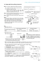
emo able Terminal lug onnection
for control input and output terminals connection
procedures.
Содержание NX-300
Страница 7: ...Chapter 1 SYSTEM SUMMARY ...
Страница 12: ...Chapter 2 INSTALLATION AND CONNECTION ...
Страница 23: ...Chapter 3 SYSTEM SETTINGS NX 300 SETTING SOFTWARE ...
Страница 113: ...Chapter 4 SETTINGS AND MANAGEMENT BY BROWSER ...
Страница 140: ...Chapter 5 SETTINGS NECESSARY WHEN USING THE NX 300 OPERATION SOFTWARE ...
Страница 163: ...Chapter 6 APPENDIX ...

