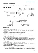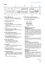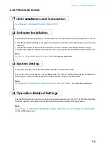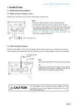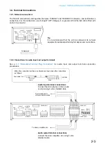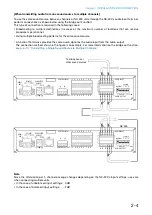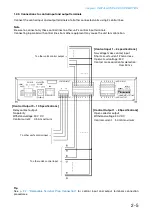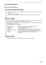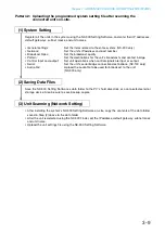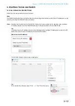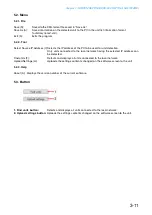
Chapter 2
INSTALLATION AND CONNECTION
2-7
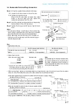
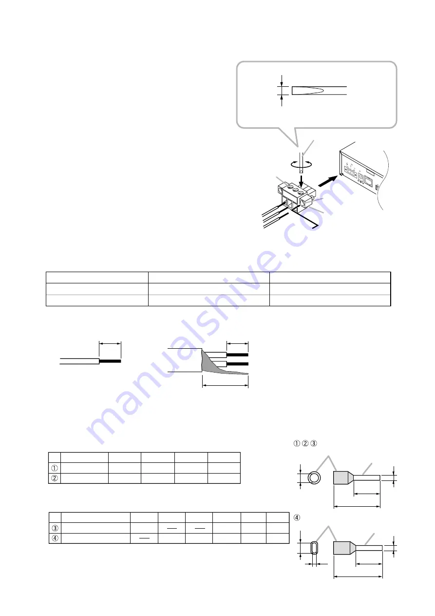
1.3. Removable Terminal Plug Connection
Solid cable and stranded cable
Shielded cable
7 mm*
2
7 mm*
2
20 mm
(0.28")
(0.28")
(0.79")
*
2
Expose 8 mm
0.31 or more hen using
the above ferrule terminal, and cut off an
e tra conductor protruding from the slee e.
Note
A oid soldering stranded or shielded cable,
as contact resistance may increase when
the cable is tightened and the solder is
crushed, possibly resulting in an e cessi e
rise in joint temperatures.
•
Cable sheath to trim
Step 1.
iring the supplied remo able terminal plug.
1-1.
Loosen the terminal screws to insert the wire.
1-2.
Tighten the terminal scre s.
nsure that the ire does not break free hen
pulled. If the wire does pull free, repeat the
connection procedure from the start.
Step 2.
nsert the ired terminal plug into the corresponding
terminal block in the unit s rear panel.
Step 3.
Tighten the ing scre
po er input terminal
only .
Notes
• o not re erse Steps 1 and abo e. oor contact may
result if force is applied to the unit s internal circuit board
pins hile the terminal scre s are being tightened.
• hen detaching the terminal plug, pull it straight out.
ulling it out at an angle may cause the terminal plug or
terminal block to break.
Fixing screw
Terminal screw
Removable terminal
plug (accessory)
Tightens
Loosens
1
2
3
Slotted screwdriver
[Recommended type of screwdriver ]
Blade width*
1
*
1
For DC power input terminal: About 3.5 mm (0.14")
For other terminals: About 2.5 mm (0.1")
10
9
CONTR
OL INPUT
1
CONTR
OL OUTPUT
24V 200mA
LAN
AC AD
APTER
DC INPUT
24V 200mA
DC INPUT
1
GND
SIGNAL
Tips
• Applicable cable si e
For DC power input terminal
For other terminals
Conductor cross-section area
0. . mm
2
0.1 1. mm
2
A
A
1 or e ui alent
A
1 or e ui alent
• hen connecting cables or a shielded cable to a single terminal, use a ferrule terminal ith an insulation
sleeve to crimp the cables because such cable conductors could become loose.
1 ecommended ferrule terminals for cables other than po er supply cables
made by hoeni ontact
ecommended ferrule terminals for po er supply cables
made by hoeni ontact
rimping tool
OX 10S made by hoeni ontact
Insulation sleeve
Contact section
Insulation sleeve
Contact section
a
l
2
a
1
a
2
l
1
l
2
l
1
b
b
Model Number
a
1
l
1
l
2
AI 1,5-8 BK
AI-TWIN 2 x 1,5-8 BK
6.6 (0.26)
a
2
3.6 (0.14)
14 (0.55)
16 (0.63)
2.3 (0.09)
8 (0.31)
8 (0.31)
a
3.4 (0.13)
Unit: mm (in)
b
1.8 (0.07)
Model Number
a
l
1
l
2
AI 0,34-8 TQ
AI 0,5-8 WH
2 (0.08)
Unit: mm (in)
2.5 (0.1)
12.5 (0.49)
14 (0.55)
8 (0.31)
8 (0.31)
b
0.8 (0.03)
1.1 (0.04)
Содержание NX-300
Страница 7: ...Chapter 1 SYSTEM SUMMARY ...
Страница 12: ...Chapter 2 INSTALLATION AND CONNECTION ...
Страница 23: ...Chapter 3 SYSTEM SETTINGS NX 300 SETTING SOFTWARE ...
Страница 113: ...Chapter 4 SETTINGS AND MANAGEMENT BY BROWSER ...
Страница 140: ...Chapter 5 SETTINGS NECESSARY WHEN USING THE NX 300 OPERATION SOFTWARE ...
Страница 163: ...Chapter 6 APPENDIX ...

