background image


Synergy Controller Technical Manual, Revision H 


Page 41 

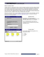
6.2.2   Altitude Value  

 
SETUP\Calibration\Altitude\Altitude Value\ 

ALT 


SETUP\Calibration\Altitude\Altitude Value\ 

sets the scaling for the pressure channel. Set the altitude value 

to 0 for linear scaling for regular pressure transducers.  For Granville-Philips transducers, set the parameter 
to 10, 11 or 12 for exponential scaling.  A Registration Key may be required to access this feature.  See 
additional details in the 

Altitude/Space Chamber Setup section

. 


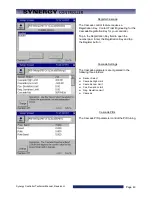
6.2.3   Guaranteed Soak 

 
SETUP\Calibration\Guaranteed Soak\ 

GS 

 
The Guaranteed Soak feature stops a program from advancing until the process variable is within the 
guaranteed soak limits. Range for this is 0 to 50 degrees. This value applies to each setpoint in the program. 
As an example, for a setpoint of 100 degrees with a guaranteed soak of 1 degree, the program will wait until 
a temperature between 99 and 101 degrees is reached before advancing, regardless of the step time. When 
enabled, the Guaranteed Soak feature will affect all setpoint steps in any profile run on the chamber.  An 
alternative to the system wide Guaranteed Soak setting is the Wait For step which provides soaking on 
specific steps of the profile.  For example, to guarantee a soak at 100C add a Ramp step to 100C then add a 
Wait For step that waits for 100C.  See the 

Program section 

of the manual for more information. 


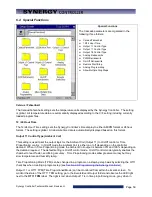
6.2.4   Input Calibration 

 
Each controller input is calibrated and scaled from this folder and sub-folders.  Raw calibration calibrates the 
controller measurement, either Volts or Ohms.  The voltage and scale and engineering scale are set for each 
sensor.  The input type is selected from the list. The High Resolution Inputs are the most accurate inputs and 
typically uses for process variables.  The Low Resolution inputs are used for machine parameters like 
pressure transducers, etc. 
 

6.2.4.1   RTD Calibration 

 
The Synergy Controller chamber accepts up to two Platinum RTD (Resistance Temperature Detector) 
sensors.  RTDs are the most linear, stable and reproducible temperature sensors available.  Over the years, 
both American and European RTD standards have been developed to ensure that RTDs are interchangeable 
from manufacturer to manufacturer.  Platinum RTDs are specified to standards such as DIN (Deutsch 
Institute fur Normung) and JIS (Japanese Industrial Standard).  These standards define the RTD 
specifications.   
 
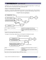
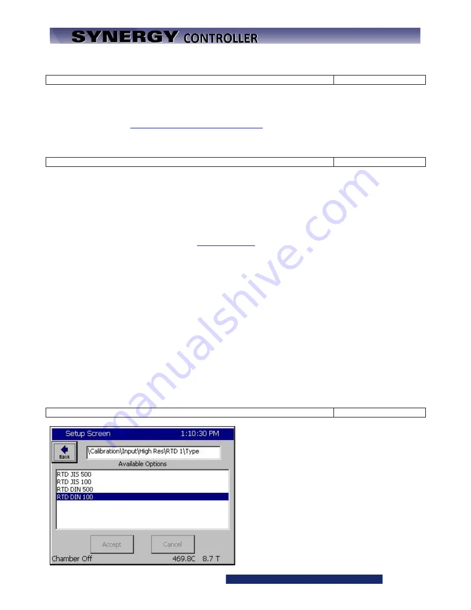
SETUP\Calibration\ Input\High Res\RTD n\Type\ 

HIGHn_TYPE 


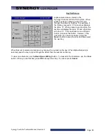
Each of the Synergy Controller’s two RTDs can be 
set for four types: 
 
RTD JIS 500 
RTD JIS 100 
RTD DIN 500 
RTD DIN 100.   
 
Note: In early software versions, the RTD curve 
was set globally so one RTD curve was used for 
both sensors. 
 

Содержание Synergy Compact

Страница 1: ...al Manual Revision H Nano Micro 2 and Quattro For One to Four Channel Systems Tidal Engineering Corporation 2 Emery Ave Randolph NJ 07869 support tidaleng com www tidaleng com Document Number TE1813 R...

Страница 2: ...4 20 mA sensor wiring section Added Space and Altitude section Added Altitude section in L Values for Altitude and Space Chamber Configuration Added LabVIEW driver section Added Deviation Alarm featu...

Страница 3: ...orms 19 3 4 Chillers 19 3 5 Other Equipment 19 4 0 EQUIPMENT SAFETY AND CONTROLLER ALARMS 20 4 1 Standard Alarm Limits 20 4 2 User Programmable Alarm Limits 20 4 3 Secondary Controller Alarms 20 4 4 A...

Страница 4: ...2 Alarm Functions 96 7 3 Channel PIDs 101 7 4 About Screen 102 7 5 File Utilities 102 7 5 1 Software Upgrade Procedures 103 7 5 2 Export Screenshots 116 7 5 3 Logging 116 7 6 Date and Time 117 7 7 Re...

Страница 5: ...NG 151 14 1 Data Logging Setup 151 14 1 1 Deliver Test Results Automatic Test Data Delivery 154 14 1 2 Profile Logging 158 14 1 3 Logging Commands 159 14 2 Logging Applications 160 14 2 1 Controller T...

Страница 6: ...17 4 3 Ethernet MAC Address 293 18 0 APPENDIX B SETTINGS LIST 297 19 0 APPENDIX C DELIVERING RESULTS 304 19 1 Network Printing 304 19 2 E Mail Delivery 305 19 2 1 E Mail Setup 307 19 2 2 E mail Forma...

Страница 7: ...uch screen technology and incorporates Screen Navigation keys and a friendly and powerful user interface The Synergy Controller supports USB Hard Disks for data logging program download upload File fo...

Страница 8: ...Alarm information enhanced i e Alarm shows source of Digital Input DIN 1 Improved Cascade Control Algorithm o Control Boost Heat and Boost Cool explicitly Command Set o 200 new commands Logging Featur...

Страница 9: ...ble below along with an icon for each Features that aren t supported by all five configurations are identified in this document with the appropriate icons Type Synergy Micro 2 Synergy Micro Synergy Mi...

Страница 10: ...configurations below are supported by prior technical manuals Rev F Synergy Compact P N TE1666 TE1530 Processor X86 Floppy Drive Yes OS P N TE1360 Synergy V P N TE1364 Processor x86 Floppy Drive Yes...

Страница 11: ...ano 3 Synergy Nano Icon P Ns TE1858 1 TE1858 2 TE1858 3 TE1858 4 Processor ARM ARM ARM ARM Main Outputs 6 Open Collector 6 Electro Mechanical Relays 6 SSRs Solid State Relays Expanded Olympic Board Au...

Страница 12: ...e Temperature Thermal Shock Chambers Generic Temperature Humidity Generic Temperature Humidity Single Stage Generic Temperature Pressure Altitude and Space Chambers Generic Temperature Humidity Pressu...

Страница 13: ...ENGINEERING PRODUCTS ARE NOT AUTHORIZED FOR USE AS CRITICAL COMPONENTS IN LIFE SUPPORT DEVICES OR SYSTEMS UNLESS A SPECIFIC WRITTEN AGREEMENT REGARDING SUCH USE IS OBTAINED FROM TIDAL ENGINEERING PRIO...

Страница 14: ...Synergy Controller Technical Manual Revision H Page 14 2 0 SPECIFICATIONS 2 1 Data Sheet...

Страница 15: ...ystem designed to handle virtually all temperature control applications The block diagram in the following section identifies the major systems of the controller and their relationships Two small bloc...

Страница 16: ...tion Channel 1 PIDs 30 Digital Outputs 2 Alarm Relay Outputs 2 Analog Outputs Channel 2 PIDs Channel 3 PIDs Channel 4 PIDs Channel Primitives User Alarm 1 User Alarm 2 User Alarm n Logging Database Se...

Страница 17: ...ate engineering units See the Calibration section 2 1 3 Channel Calibration Each Channel is assigned an input In addition channel data can be scaled and offset to accommodate Channel errors caused by...

Страница 18: ...tion 6 14 for details 2 1 8 Logging System The logging system is used to capture test results and chamber performance data as well as alarm conditions The logging system can acquire data from any cont...

Страница 19: ...process oven applications in manufacturing operations Data logging and printing E mail alarms and chart data delivery Bar code reader features for error proof setup 3 3 Thermal Platforms Thermal plat...

Страница 20: ...n alarms a secondary controller should always be employed to offer further protection in the case of sensor or controller failure 4 1 Standard Alarm Limits The Synergy Controller features standard hig...

Страница 21: ...resent ALARM flashes in the upper right corner of the touch screen Alarm status is displayed in the lower left hand corner of the touch screen Alarms are listed in the Alarm folder in the Maintenance...

Страница 22: ...mber of software keys and a front accessable USB Host port The principal components of the Synergy Controller Interface Panel are identified in the layout below Synergy Controller Front View Comm Acti...

Страница 23: ...tor Manual Mode Operating Screen w Small Graphic Display PID Settings Alarms RS 485 UUT Temps Special Functions Channel PIDs IEEE 488 Digital Outputs L Values About Ethernet Digital Inputs LCD Setting...

Страница 24: ...tifies the common elements of the Synergy Controller display The title bar at the top and the status bar at the bottom of the window are found on most screens Keypad Screen Example The screenshot belo...

Страница 25: ...t screen and store it to a USB Hard Disk After pressing the key the window at the left will appear The picture will be saved in memory To export the bitmap to your storage media go to the Maintenance...

Страница 26: ...ter Name Valid Range Present parameter value New paramter value Clear Cancel can Accept keys Numeric Values Alpha Numeric and Symbol Keypad Example The Alpha Numeric keypad is based on the T 9 pad use...

Страница 27: ...igate away from a screen and return the folder remains in the state that it as in For example you can navigate to the MAIN screen while entering a parameter in the SETUP screen and when you navigate b...

Страница 28: ...ation Logging Special Functions L Values Chamber Setup Resume Behavior User Alarms Main Screen Setup and Event Screen The Administrator can use the Panel Lock and Languages screens to control access t...

Страница 29: ...ilities Data and Time and Restart Screens The Administrator will typically use the File Utilities to Backup and Restore the controller settings and set the Data and Time using that folder The Engineer...

Страница 30: ...r the RS 232 The RS 485 port is used to setup the connection to the UUT Thermocouple modules The IEEE 488 folder is used for the setup of that port The Ethernet Network folder is used to setup the net...

Страница 31: ...y OEMs and technicians administrators and engineers to load save create and edit controller programs PROGRAM Screen Create a New File Open and Existing File Save the Loaded File Edit a program step Ad...

Страница 32: ...Run screen is used by engineers and operators to load control and monitor programs RUN Screen Open File Run Run From from a selected step Run Off program with outputs off Stop Pause Dynamic Edit Deta...

Страница 33: ...e Thermocouple from the UUT Thermocouple monitoring system The Digital Outputs folder is a visual display of all of the controller outputs and the Digital Inputs folder is a visual display of all of t...

Страница 34: ...the equipment The Graph scaling X and Y can be adjusted in the SETUP Graph Settings folder GRAPH Screen Screen Information Graph channel actual and setpoint values over time Control Features Access t...

Страница 35: ...tup Folder MAIN Screen The Main screen is the first screen that appears after power up Use this screen to operate the chamber in steady state mode Screen Information Actual values for each chamber cha...

Страница 36: ...and a third time will show C If the next letter is on a different button just press that button However if the next letter is on the same button press the Next button to save the entry and then selec...

Страница 37: ...ock Languages User Alarms Resume Behavior Main Screen Setup Event Screen Setup Some of the parameters in the Setup Directory are preset by the installer or equipment manufacturer Under most circumstan...

Страница 38: ...Calibration The SETUP Calibration Calibration Channel n Screen contains all of the setup and calibration parameters for channel n There is a Calibration Channel folder for each channel with the follo...

Страница 39: ...imits can be disabled automatically when the Channel is off using the Ignore Alarm When Off parameter Alternatively the Absolute Alarms can be delayed using the Channel Alarm Delay Deviation High Alar...

Страница 40: ...lution Inputs RTD 1 RTD 2 Analog 1 Analog 2 Analog 3 Analog 4 TC 1 TC 2 UUT Up to 64 T type T Cs Module 1 Thru 8 Sensor 1 thru Sensor 8 Machine Inputs Low Resolution Inputs Low Res 1 thru 8 Digital In...

Страница 41: ...to guarantee a soak at 100C add a Ramp step to 100C then add a Wait For step that waits for 100C See the Program section of the manual for more information 6 2 4 Input Calibration Each controller inpu...

Страница 42: ...Calibration Input High Res Analog n Raw Calibration Offset HIGHn_OFF Set the Raw Calibration gain and offset to calibrate controller Use the Two Point calibration calculation formula section 16 to cal...

Страница 43: ...Compensation T RH Raw a0 a1 b0 b1 A B Vaisala RH Corrected 60 70 1 53646 0 034144 0 889657 0 002452 0 51218 1 036777 73 105 60 80 1 53646 0 034144 0 889657 0 002452 0 51218 1 036777 83 473 60 100 1 53...

Страница 44: ...ure sensors as an alternative to an electronic RH sensor To make these measurements a wet bulb sensor infers the amount of moisture in the air when the evaporation from a moist cloth wick placed over...

Страница 45: ...ETUP Calibration Virtual Sensors Wet Bulb Dry Bulb Wet Bulb Input Filter WBIN_FLT_ENABLED SETUP Calibration Virtual Sensors Wet Bulb Dry Bulb Wet Bulb Input Filter WBIN_FLT_ENABLED SETUP Calibration V...

Страница 46: ...threshold and hysteresis which SETUP Calibration Virtual Sensors Virtual Pressure Std Range Pres Sensor ID VP_STDALT_SENID SETUP Calibration Virtual Sensors Virtual Pressure High Alt Pres Sensor ID V...

Страница 47: ...Heating Reset Channel n Heating Rate Channel n Heating Cycle Time for Ch n Heating Rate Band for Ch n Heating Where n is the Channel SETUP PID Settings PID Ch n PID Ch n Heat Prop Band Ch n Heat PBnH...

Страница 48: ...r than just the air temperature Cascade control provides greater test accuracy in addition to faster and more efficient ramps and soaks Because the Cascade control is a powerful feature of the Synergy...

Страница 49: ...Key for your controller Tap in the Registration Key field to open the number pad Enter the Registration Key and tap the Register button Cascade Settings The Cascade parameters are organized in the fo...

Страница 50: ...11 Control Type Ambient Coil This setting is used to set the output logic for the Ambient Coil Output 11 to On Off control or Time Proportioning control In On Off mode the Ambient Coil is either on o...

Страница 51: ...e mode Use vacuum when channel 2 units are in Torr Output 17 Vacuum Logic Diagram OT17 Output 17 Control Type Selects the control logic for the Vacuum device Can be either Vacuum or Purge LEV 2 Contro...

Страница 52: ...n eliminate the need for a conventional chart recorder The Synergy Controller features two analog signals called Analog Retransmit 1 and 2 that can output setpoints actual process data and internal PI...

Страница 53: ...its Select the PWM Retransmit 1 folder to open the data output mapping options The parameters for each PWM are Retransmit Source High Eng Scale Low Eng Scale High Duty Cycle Low Duty Cycle Cycle Time...

Страница 54: ...ntroller On and Off remotely Analog Programming The Analog Programming Feature parameters are Programming Enabled Analog Input Select When Analog Programming is enabled the controller setpoints can be...

Страница 55: ...B1H Reset Ch1 Heating RS1H Rate Ch1 Heating RT1H Cycle Time Ch1 Heating CT1H Rate Band Ch1 Heating RB1H Dead Band Ch1 DB1 Proportional Band Ch1 Cooling PB1C Reset Ch1 Cooling RS1C Rate Ch1 Cooling RT1...

Страница 56: ...2 L Values 1L1 Ch1 Main Cooling Turn On 1L1 1L2 Ch1 Main Cooling Turn Off 1L2 1L3 Ch1 Setpoint Transfer Setting 1L3 1CTY Ch1 Chamber Type 1CTY 2L1 Ch2 Main Cooling Turn On 2L1 2L2 Ch2 Main Cooling Tur...

Страница 57: ...1L3 Ch1 Setpoint Transfer Setting 1CTY Ch1 Chamber Type 2L1 Ch2 Main Cooling Turn On 2L2 Ch2 Main Cooling Turn Off 2L3 Ch2 Setpoint Transfer Setting 2CTY Ch2 Chamber Type Temperature Humidity Tempera...

Страница 58: ...Turn On Cooling output required to turn on channel 2 cooling 0 to 100 2L2 Ch2 Main Cooling Turn Off Heat output required to turn off channel 2 main cooling 0 to 100 2L3 Ch2 Setpoint Transfer Setting A...

Страница 59: ...midify device 0 to 100 L14 Time Delay Boost Cool Time delay required before Boost Cool is enabled 0 to 1200 seconds L15 Compressor Turn Off Delay Delay required before turning off a compressor 0 to 5...

Страница 60: ...test documentation 6 7 1 Logging Setup This section describes the Log system setup options and steps Note Before starting a test that requires logging you should consider whether you want to export a...

Страница 61: ...gy Controller Technical Manual Revision H Page 61 The screen at the left appears The following data is available for logging Channel Readings Actual Channel Setpoints Channel PIDs Machine Values UUT V...

Страница 62: ...Change button Step 4 Select the Channel PIDs Folder Control the logging of the Heat and Cool PIDs for Channel n from this screen These values can be viewed in the Channel PIDs screen of the Maintenanc...

Страница 63: ...es can be viewed in real time in the UUT Temperatures screen of the Events directory Select the UUT and press the Change button Scroll down to access UUTs 6 8 Return to the Logging directory by pressi...

Страница 64: ...detected the Synergy Controller will automatically export the file When the export is complete it will confirm a successful export and prompt to close the window by pressing the OK button Your export...

Страница 65: ...as The table below lists the information that can be logged Each data type requires a specific amount of storage space on the Storage Card In addition there are a number of overhead bytes per sample f...

Страница 66: ...igh Stage Pressure Hi Side Machine Sensor 8 4 bytes High Stage Temperature Hi Side UUT Device 1 56 bytes 8 Thermocouple readings UUT Device 2 56 bytes 8 Thermocouple readings UUT Device 3 56 bytes 8 T...

Страница 67: ...essure Generic Temperature Vibration Retro Temperature Only The Chambers Types in the list above that are identified with support VersaTenn retrofit fit applications WARNING Incorrect Chamber Type set...

Страница 68: ...1SM J5 connector as shown at the right In addition some chamber definitions provide the same function to more than one output This is referred to as mirroring For example in the Generic Temperature H...

Страница 69: ...gure in the installation section of this manual 6 11 Panel Lock Panel Lock is a security feature that either partially or completely restricts access to the Synergy Controller This feature can protect...

Страница 70: ...Lock Feature Setup To setup the Panel Lock feature follow these steps 1 Specify the password for each user level 2 Specify the user level for each of the 8 Screens 3 Set the Panel On Off Keys as requ...

Страница 71: ...Synergy Controller Technical Manual Revision H Page 71...

Страница 72: ...ns and passwords The panel lock options control the function of Panel Lock in two ways 1 Panel On Off Keys Enable Disable 2 Unlock Timer Duration 1 Panel On Off Keys when set to Enable allow the use o...

Страница 73: ...ings folder in the order of access privilege The Administrator password has the highest privilege and can access all the controller screens The password can be up to 10 alpha numeric characters To cha...

Страница 74: ...n Default Access SETUP Administrator MAINT Maintainer COMM Engineer PROG Engineer RUN Operator EVENTS Operator GRAPH Unrestricted MAIN Operator The Panel Lock Screen Settings folder is shown below Not...

Страница 75: ...purposes only 6 13 User Programmable Alarm System The Synergy Controller s user programmable alarm system can create customer specific alarms and warnings and special factory applications The user can...

Страница 76: ...ilable Comparison Application Input Open Digital Inputs only Input Closed Digital Inputs only Greater than Threshold All inputs except Digital Raw or Scaled Less than Threshold All inputs except Digit...

Страница 77: ...tup Screen and browse to the User Alarms folder Select the Sensor Setpoint or channel Define the comparison type and the scaling The Comparison choices are 1 Input Open 2 Input Closed 3 Greater than 4...

Страница 78: ...ep is not required for Digital Inputs Enter a name for the alarm This name appears in the alarm screen when the alarm occurs and in the alarm list Select the desired alarm response The Options are 1 S...

Страница 79: ...h User Alarm Example 1 Create an alarm that senses Digital Input 5 and Displays Oxygen Sensor Warning when the input is Open Open the User Alarm folder and press the Add Alarm button on the Setup scre...

Страница 80: ...sion H Page 80 Press the Sensor text box as shown at left to start the Sensor Selection process Select Digital Input 5 as shown in the figure at left and then press accept The wizard displays the code...

Страница 81: ...81 Select the Comparison from the drop down window In this case Input Open Note Data Scaling doesn t apply for digital inputs Then press Next Enter a name for this alarm Press the text box to open the...

Страница 82: ...ical Manual Revision H Page 82 Then press Next Select the Alarm Actions In this case the Show Alarm and Log Alarm options are selected Then press Next Confirm your choices and press Finish to complete...

Страница 83: ...shows the new entry In operation the Alarm Screen in the Maintenance folder indicates a normal state when the Input is closed as shown in the figures below The Alarm Screen in the Maintenance folder...

Страница 84: ...tes Yes in the Ack column after an alarm is acknowledged The alarm indicates Yes in the Cleared column after it has been cleared i e the alarm condition is no longer present As with built in alarms us...

Страница 85: ...H Page 85 For example in the screenshot below the Alarm has been acknowledged but the alarm condition still exists Once the Alarm has been acknowledged and the alarm condition has cleared the alarm e...

Страница 86: ...and opens Relay 2 when the value is less than 30 Torr This alarm is named Heater Safety Shutoff and displays Heater Safety Shutoff when the threshold is reached Open the User Alarm folder and press th...

Страница 87: ...Scaled Value for Data scaling because we want to check the scaled Torr value as opposed to the Raw 0 5 Volt input value Then we press Next to continue Next we enter the Alarm Threshold Press the Alar...

Страница 88: ...ion H Page 88 Confirm the Alarm Threshold Then we press Next to continue Here we enter the Alarm response In this case we only want to Activate Relay 2 Then we press Next to continue And finally we co...

Страница 89: ...operation when the Torr value is greater than 30 Torr as shown here Relay 2 Event 24 is Activated Grey When the Torr value is less than 30 Torr as shown here Relay 2 Event 24 is normal Red Note that...

Страница 90: ...e mode Profiles parameter controls the behavior when the controller power is lost while the controller is running a Program Restart Delay parameter is used to delay the chamber restart to limit the cu...

Страница 91: ...y Controller Technical Manual Revision H Page 91 Large Medium Small Channel Text sizes Large Display Channel Text Small Display Channel Text Medium Display Channel Text Small Display Channel Text with...

Страница 92: ...Synergy Controller Technical Manual Revision H Page 92 6 15 2 Sensor Displays Up to 8 Sensors Medium Display Channel Text Sensor 3 Sensor 6 Sensor 5 Sensor 4 Sensor 7 Sensor 8 Sensor 9 Sensor 10...

Страница 93: ...Synergy Controller Technical Manual Revision H Page 93 6 15 3 Chamber Light Main Screen Setup Folder Chamber Light with Large Display Text Chamber Light Folder Chamber Light with Medium Display Text...

Страница 94: ...ameters that pertain to Humidity control features can be hidden allowing Event 7 Event 8 and Event 9 to be displayed The Event Screen can be customized to display user friendly names rather than just...

Страница 95: ...to view and clear a chamber alarm When an alarm occurs the following attributes are listed Time of Alarm Alarm Type Ack User acknowledgement Cleared Indicates if the alarm condition has cleared The wo...

Страница 96: ...osed YES No 2 Low Program Memory RAM Closed Closed YES No 3 Temp guard Closed Closed YES No 4 Open Sensor Ch1 RTD 1 OPEN Closed YES YES 5 Open Sensor RTD 2 Closed Closed No No 6 Voltage Sensor Ch 2 Hu...

Страница 97: ...an alarm condition when the space remaining is less than 160K When this occurs you can clear the log file export screenshots or remove programs from the Storage Card to free up Storage Memory to corre...

Страница 98: ...gging data cannot be recovered Go to the Setup Screen and select the Logging Clear History folder Press the Clear History button to delete the current history file and free its space on the Storage Ca...

Страница 99: ...u have cleared the alarm condition you can acknowledge the alarm to remove it from the Alarms folder list To acknowledge the Low Storage alarm go to the Maintenance Screen and select the Alarms folder...

Страница 100: ...etup folder Select Log File Size and press the Change button The Synergy Controller determines the upper limits of the valid range automatically Change the Log File Size to a number below the maximum...

Страница 101: ...al temperature of the product inside the chamber Setpoint Actual values under Heating and Cooling is air temperature Setpoint value under Heating and Cooling is the calculated air temperature setpoint...

Страница 102: ...Input Output processor board It acquires analog and digital inputs and controls the outputs that drive the chamber components The Serial Number on the Olympic Board is required for technical support a...

Страница 103: ...e upgrade In addition you may want to manually record your Cascade and Web Server registration keys if your chamber employs those features as well as the Chamber Type so these can be restored after th...

Страница 104: ...104 Then select either the Storage Card or the USB Hard Disk from the Drive List and Then press the File Text Box Enter the File Name using the T9 Pad Then press OK Confirm the file name that appears...

Страница 105: ...n at the left Acknowledge the window by pressing OK Step 2 Install the New Software Copy the zip file to a temporary directory on your PC Place a USB Flash Disk key in the USB port on your PC Double c...

Страница 106: ...Synergy Controller Technical Manual Revision H Page 106...

Страница 107: ...on H Page 107 Select Extract Files and browse to the USB Flash Disk on your PC as shown below In this example the drive is named Removable Disk F After the files are extracted you will see the Upgrade...

Страница 108: ...Maintenance Screen Open the File Utilities Folder and press the Upgrade Software folder Make sure the USB Flash Disk is in the Controller s USB port and press the Upgrade Software button It may take a...

Страница 109: ...Configure the Controller When the chamber restarts the controller may indicate that the current chamber type differs from the last chamber type Press OK to acknowledge the message The Dialog will ask...

Страница 110: ...r type This is OK Press OK to acknowledge that message You will then be asked if you would like to discard the old settings and load the current settings Press YES on this window Restore Settings In t...

Страница 111: ...rive List Then select the appropriate file from the list and press Select Confirm the File Name that appears in the Restore File text box and then press Restore The Controller will confirm that the se...

Страница 112: ...S 485 RS 485 Mode Station Address Number of UUTs Note These RS 485 settings are important for UUT Thermocouple Modules IEEE 488 IEEE 488 Address Ethernet IP Address Selection Ethernet Address Ethernet...

Страница 113: ...eating PB1H Reset Ch1 Heating RS1H Rate Ch1 Heating RT1H Cycle Time Ch1 Heating CT1H Rate Band Ch1 Heating RB1H Dead Band Ch1 DB1 Proportional Band Ch1 Cooling PB1C Reset Ch1 Cooling RS1C Rate Ch1 Coo...

Страница 114: ...1L1 Ch1 Main Cooling Turn On 1L1 1L2 Ch1 Main Cooling Turn Off 1L2 1L3 Ch1 Setpoint Transfer Setting 1L3 1CTY Ch1 Chamber Type 1CTY 2L1 Ch2 Main Cooling Turn On 2L1 2L2 Ch2 Main Cooling Turn Off 2L2...

Страница 115: ...Registration Keys optional Web Server Registration Key Cascade Registration Key Pressure Registration Key Note These alphanumeric keys were provided if you purchased these features If you do not have...

Страница 116: ...oller Technical Manual Revision H Page 116 7 5 2 Export Screenshots Select the Export Screenshots folder Tap Browse Select the USB Flash Disk and tap Export 7 5 3 Logging See Logging features in Secti...

Страница 117: ...just the date and time and press the Apply button 7 7 Restart Restart Controller It is necessary to restart the controller during some chamber setup procedures This can be done by cycling power to the...

Страница 118: ...Set 8 1 Communications Folder Communications Folder Select the following communication functions RS 232 RS 485 IEEE 488 Ethernet Network 8 2 RS 232 RS 232 RS 232 communications are standard on all Sy...

Страница 119: ...The IEEE 488 port may be used with third party test and measurement software such as LabVIEW Tidal Engineering s Synergy Manager or Tidal Engineering s SimpleComm 8 5 Ethernet Network Ethernet Networ...

Страница 120: ...may not work on your network 8 5 2 WebTouch Remote Web Server The web server allows you to remotely control monitor and run diagnostics on chambers over the web using Microsoft s Internet Explorer web...

Страница 121: ...e mails automatically to desktop computers and mobile phones and tablets E Mail is supported on the software application Version 3 0 7 Build 893B and newer Contact the Tidal Engineering if you are int...

Страница 122: ...Network E Mail Addresses E Mail Enter up to five E Mail addresses or Cell Phone numbers as shown on the left 8 5 6 Printer Setup Printer Setup Setup the Network Printer parameter as shown on the left...

Страница 123: ...Synergy Controller Technical Manual Revision H Page 123...

Страница 124: ...er and from the Tools menu select Internet Options Press the Settings button under Temporary Internet Files In the Settings screen select the Every visit to the page option Press OK to save the config...

Страница 125: ...word list If you don t save the password you will be prompted for a password each time you open a new session After you have successfully logged in you will see the web interface exactly as it appears...

Страница 126: ...that make up the profile The following command buttons are explained with example screens that follow New File Clears current program Open File From Storage Card or USB Save File To Storage Card or U...

Страница 127: ...r program See Section 10 for details 9 2 Creating a New Program The Add Step Wizard is Synergy Controller s step by step guide for adding and inserting program steps Each function is defined with on s...

Страница 128: ...chnical Manual Revision H Page 128 3 Select Step Type 4 Temperature Control 4 Enter Temperature Setpoint Press Accept 5 Humidity Control 6 Enter Humidity Setpoint and Press Accept 7 Specify a Ramp Tim...

Страница 129: ...Synergy Controller Technical Manual Revision H Page 129 8 Enter Ramp Time 9 Turn On Off Events External Outputs 10 Finish 11 View Completed Step...

Страница 130: ...tep For example if the user wants to ramp the temperature ten degrees in ten minutes the chamber will drive the temperature one degree higher every minute Output Events are programmable for each step...

Страница 131: ...open Only digital inputs that are not ignored are checked By default all inputs are ignored unless specified Auto Start The Auto Start step is used to automatically start the chamber The profile can...

Страница 132: ...pes Temp only Temp Humidity Temp Temp Temp Pressure S T E P No S T E P Type Setpoint s Time Events X ON D r y e r C o p y S t e p Jump Loop WAITFOR AUTOSTART S T O P Temp Hum Temp Press SP1 SP2 Hrs Mi...

Страница 133: ...he Edit Step Wizard will guide through step editing Step editing is the same procedure used by the Add Step Wizard Delete Step The Wizard will ask you if you are sure you wish to delete the current st...

Страница 134: ...ct the desired file from the Drive List File List screen that appears 10 2 Program Control Run Press the Run button to start the loaded program at the first step Run From Use this button to start the...

Страница 135: ...umeric keypad and enter the new number of jump loops to perform and press OK Press Run or Run Off to resume running the program Note Enter 1 to exit the loop Note If the chamber loses power while runn...

Страница 136: ...Purge or Chamber Light For example test engineers can use these Event Outputs to enable disable power to the Unit Under Test UUT for certain portions of a profile enable LN2 solenoids or operate some...

Страница 137: ...ature is used to change the dehumidification method The Chamber defaults to Dehumidify Coil Select the Use Drier method to achieve very low humidity The Use Drier mode is controlled by the settings in...

Страница 138: ...etpoint step To monitor the state of the OT11 TPM setting go to the Events Event Output folder and observe the LED indicator next to the OT11 TPM label The light is red when the time proportioning mod...

Страница 139: ...the 20 pin connector J2 on the event output board 2 Connect the other end of the 20 pin cable to the 20 pin connector on the back of the Synergy Controller P6 See the figure below Event Board Connect...

Страница 140: ...Synergy Controller You can control them locally through the touch panel through remote software such as the Synergy Manager software or within a chamber profile The instructions that follow describe...

Страница 141: ...Synergy Controller Technical Manual Revision H Page 141 TE1151 6 Triac Output Board Schematic...

Страница 142: ...Synergy Controller Technical Manual Revision H Page 142 TE1708 6 Relay Board Schematic...

Страница 143: ...output Grey LED Output Off On Off type Red LED Output On On Off type Yellow LED Time Proportioning Type The information bar at the bottom indicates the output designation and the status of the select...

Страница 144: ...Output 10 drives the fan device The output maps for each chamber type are listed in Section 15 11 4 Digital Inputs The Digital Input Screen displays the status of inputs from up to 16 switch closures...

Страница 145: ...e Browse to the Calibration Input High Res folder in the Setup screen to set the scaling for these inputs 11 6 Low Resolution Analog Inputs Low Resolution Analog Inputs Analog 1 Volts Analog 2 Volts A...

Страница 146: ...rature Humidity Air Temperature Graph Options Select the individual checkboxes to display specified graph lines Temperature displays the air temperature inside the chamber Humidity displays the humidi...

Страница 147: ...ontroller is powered up Steady state set points are accessed from this screen The chamber can also be turned On and Off from this screen 13 1 1 Entering a set point Press the MAIN Navigation Screen bu...

Страница 148: ...n the graph The graph settings window will open with the following graph data selection options Actuals process data Temperature Actual Humidity Actual Air Temperature Actual Cascade Setpoints Tempera...

Страница 149: ...d displayed on the MAIN screen as shown below Tapping the Chamber Light Icon will change the state of the Event 13 2 3 Channel Text Three Channel text size options are available for the MAIN screen as...

Страница 150: ...dditional sensor values can be displayed on the Main screen for UUT test and other variables Up to 8 Sensor Displays can be shown on the Main screen as shown below Up to 8 Sensors Medium Display Chann...

Страница 151: ...ermocouple data Alarms Profile Test data UUT Data Acquisition Chamber control performance Other Sensors And Delivers these results Network Plotting to Color Printers USB Flash Drive Synergy Server FTP...

Страница 152: ...o log when the chamber is Off otherwise interval logging will not occur when the chamber is off Logging Options Parameters Log Full Behavior The controller can be programmed to stop logging or overwri...

Страница 153: ...from the front mounted USB port with a USB flash drive Profile Naming Format Selects either the Profile file name format or the Chamber Profile file name format Note that time and date information is...

Страница 154: ...t and Log format thru the network as follows Deliver Test Log to e mail Deliver Test Plot to Printer Deliver Plot to e mail Deliver Test Log to Synergy Server Deliver Test Plot to Synergy Server Set e...

Страница 155: ...annel Readings PV and Set Points SP can be enabled individually as required The Channel Deviation Limits and Cascade Control variables for each channel can be enabled as required The Deviation Limits...

Страница 156: ...T Thermocouple sensors up to 64 and the High Resolution Analog inputs can be logged Low Resolution Analog inputs on the full sized controllers which are typically used to monitor compressor pressures...

Страница 157: ...Logging Actions screen lists the test results stored on the controller and provides a set of actions that can be performed on them Logging Status The Logging Status screen provides information about...

Страница 158: ...ity These features include E Mail Delivery see Application note Network Plotting Printing see Application note Synergy Server see Application note 99 FTP see Application note USB Flash Drive Export se...

Страница 159: ...n M Bytes LOG_FILE_SIZE 1 4 LOG_WHILE_OFF Controls whether the controller continues to log when the chamber is off LOG_WHILE_OFF 0 LOG_CHn_ACT Controls whether the controller logs the Channel n Actual...

Страница 160: ...plains how to setup the logging system and run a test to benchmark the system performance for analysis As an example to setup the controller logging system to capture PID tuning information Go to the...

Страница 161: ...that this folder may have up to four Setpoints listed PID Output Enable PID Output Logging for CH1 Cool and Heat folder These constants can optionally be logged Proportional Band a PID Constant Reset...

Страница 162: ...rt the log file to a USB Flash drive from the SETUP Logging Export History Folder on the Setup screen To plot the test results import the log file into Excel and chart it or use the controller s plott...

Страница 163: ...ntified in the table below Parameters Example Chamber Name nano th 10 Application Version 3 0 7 Build 893b Help Version 3 0 5 Operating System Version 5 0 C Olympic Version V3 0 48 Serial Number 12 12...

Страница 164: ...er startup etc Message records recorded whether Logging is Enabled of not Example Message Record Date and Time Message 08 30 2013 12 45 52 M C 85 0 100 0 85 0 85 0 Stop Running Profile LVTH10 vpl Here...

Страница 165: ...Date Time 08 30 2013 20 53 46 c 2012 Tidal Engineering Corporation www tidaleng com Date and Time Record Type Temperature Units CH1 Actual CH2 Actual CH1 Setpoint CH2 Setpoint 08 30 2013 12 39 50 M C...

Страница 166: ...12 42 14 I C 67 6 100 0 68 0 66 5 08 30 2013 12 43 14 I C 85 0 100 0 85 0 85 0 08 30 2013 12 44 14 I C 85 0 100 0 85 0 85 0 08 30 2013 12 45 14 I C 85 0 100 0 85 0 85 0 08 30 2013 12 45 52 M C 85 0 1...

Страница 167: ...UUT Module Applications The UUT module can be used to monitor and record multiple air temperatures and multiple product temperatures The controller can also control from any one of the UUT Sensor inp...

Страница 168: ...le Specifications Up to four UUT Modules can be used with the Synergy Controller Each module can accept up to 16 thermocouple inputs for a total of 64 inputs The UUT module uses Type T Thermocouples R...

Страница 169: ...opriate opening to avoid pinching 6 Plug in the UUT Module wall power transformer to a 120 Volt outlet Verify that the green LED on the UUT Module is illuminated It should be on steadily Notes The tab...

Страница 170: ...thermocouple temperature readings Press the EVENTS Navigation key on the Synergy Controller Open the UUT Temperature folder to display the screen below Remember that each UUT Module can accept up to...

Страница 171: ...3 P3 4 TC7 P3 5 P3 6 TC8 P3 7 P3 8 TC9 P3 9 P3 10 TC10 P3 11 P3 12 TC11 TC16 THERMOCOUPLE CONNECTION TABLE SENSOR Term Term TC11 P4 1 P4 2 TC12 P4 3 P4 4 TC13 P4 5 P4 6 TC14 P4 7 P4 8 TC15 P4 9 P4 10...

Страница 172: ...en an alarm occurs it generates a message record For example Ch 1 High 500 00 C is in the last field of the record as shown below 08 27 2013 16 54 39 M C 500 0 100 0 500 0 30 0 Ch 1 High 500 00 C 08 2...

Страница 173: ...of the six steps summarized here 1 Configuration selection Select the appropriate configuration for your test chamber i e Temperature Humidity Temperature Pressure etc 2 Mount the controller and the o...

Страница 174: ...eneric Temperature Humidity Pressure 7 Generic Temperature Vibration 8 Retro Temperature Only Custom configurations can be created upon request at Tidal Engineering one of our OEMs or one of the Syner...

Страница 175: ...Cool 9 9 Low Artificial Load 10 10 Cascade 11 17 Not Used 12 18 Not Used 2SM Outputs TE1151 6 SM Channel Digital Output Device 1 11 Not Used 2 12 Not Used 3 13 Not Used 4 14 Not Used 5 15 Not Used 6...

Страница 176: ...ut 3 Boost Heat High Artificial Load High Stage Compressor Cascade Condenser See Section 6 7 Device Primitives etc Burn in Logic Input 4 Enables Low Stage Compressor and Full Cool with LEV1 AGREE Cham...

Страница 177: ...D Cool 8 8 Compressor 9 9 Artificial Load 10 10 Fan 11 17 Event 1 12 18 Event 2 2SM Outputs TE1151 6 SM Channel Digital Output Device 1 11 Not Used 2 12 Not Used 3 13 Not Used 4 14 Not Used 5 15 Not U...

Страница 178: ...Input 9 None TempGard Alarm displays in Alarm Folder and Log File Alarms Name Sensor Sensor Code Default Threshold Report Log K1 K2 Hi Alarm Ch 1 RTD1 110 500 C Yes Yes Yes No Low Alarm Ch 1 RTD1 110...

Страница 179: ...8 8 Full Cool 9 9 Low Artificial Load 10 10 Cascade 11 17 Vent BC 12 18 Vacuum 2SM Outputs TE1151 6 SM Channel Digital Output Device 1 11 Ambient 2 12 PID Humidify 3 13 Hi Al 4 14 Dehumidify Coil 5 15...

Страница 180: ...on 6 7 Device Primitives etc Burn in Logic Input 4 Enables Low Stage Compressor and Full Cool with LEV1 AGREE Chamber Logic Input 5 Locks out Low Stage Compressor and enables High Stage Compressor and...

Страница 181: ...D Cool 8 8 Full Cool 9 9 Ambient 10 10 PID Humidity 11 17 Dehumidify Coil 12 18 Drier 2SM Outputs TE1151 6 SM Channel Digital Output Device 1 11 Not Used 2 12 Not Used 3 13 Not Used 4 14 Not Used 5 15...

Страница 182: ...Stage Compressor Cascade Condenser See Section 6 7 Device Primitives etc Burn in Logic Input 4 Enables Low Stage Compressor and Full Cool with LEV1 AGREE Chamber Logic Input 5 Locks out Low Stage Com...

Страница 183: ...r 7 7 PID Cool 8 8 Full Cool 9 9 Low Artificial Load 10 10 Cascade 11 17 Vent BC 12 18 Vacuum 2SM Outputs TE1151 6 SM Channel Digital Output Device 1 25 Not Used 2 26 Not Used 3 27 Not Used 4 28 Not U...

Страница 184: ...ificial Load High Stage Compressor Cascade Condenser See Section 6 7 Device Primitives etc Burn in Logic Input 4 Enables Low Stage Compressor and Full Cool with LEV1 AGREE Chamber Logic Input 5 Locks...

Страница 185: ...provides examples CAUTION The Analog inputs on the controller will be damaged if the 10 V Granville Philips output is attached without a voltage divider The setup consists of the following 5 steps 1...

Страница 186: ...ic Board Connector Pin Reference Analog Input 1 See Note P2 1 P2 7 Analog Input 2 P2 5 P2 7 Analog Input 3 P2 6 P2 7 Analog Input 4 P2 11 P2 7 Note High Resolution Analog 1 should always be connected...

Страница 187: ...tep 4 Select the channel sensor SETUP Calibration Calibration Channel 2 Select Analog 1 for sensor CH2 Sensor Select code 130 Step 5 Setup the Altitude calibration constant based on the Granville Phil...

Страница 188: ...Synergy Controller Technical Manual Revision H Page 188...

Страница 189: ...ince pressure is not controlled Pressure is recorded in the log file in Torr in scientific notation To verify setup and calibration verify the values in the following table Output in Torr is 10 Vhires...

Страница 190: ...7 7 PID Cool 8 8 Full Cool 9 9 Low Artificial Load 10 10 Cascade 11 17 Vent BC 12 18 Vacuum 2SM Outputs TE1151 6 SM Channel Digital Output Device 1 11 Ambient 2 12 PID Humidity 3 13 Dehumidify Coil 4...

Страница 191: ...ondenser See Section 6 7 Device Primitives etc Burn in Logic Input 4 Enables Low Stage Compressor and Full Cool with LEV1 AGREE Chamber Logic Input 5 Locks out Low Stage Compressor and enables High St...

Страница 192: ...ic Enable 9 9 Pneumatic Initiate 10 10 Not Used 11 17 Not Used 12 18 Not Used 2SM Outputs TE1151 6 SM Channel Digital Output Device 1 25 Not Used 2 26 Not Used 3 27 Not Used 4 28 Not Used 5 29 Not Use...

Страница 193: ...one TempGard Alarm displays in Alarm Folder and Log File Alarms Name Sensor Sensor Code Default Threshold Report Log K1 K2 Hi Alarm Ch 1 RTD1 110 500 C Yes Yes Yes No Low Alarm Ch 1 RTD1 110 200C Yes...

Страница 194: ...9 9 Not Used 10 10 Not Used 11 17 Not Used 12 18 Not Used 2SM Outputs TE1151 6 SM Channel Digital Output Device 1 1 Not Used 2 2 Not Used 3 3 Not Used 4 4 Not Used 5 5 Not Used 6 6 Not Used 3SM Event...

Страница 195: ...w Eng Scale N A N A N A N A Digital Inputs Name Input Function when Closed TempGard Input 9 None TempGard Alarm displays in Alarm Folder and Log File Alarms Name Sensor Sensor Code Default Threshold R...

Страница 196: ...cribed in the previous sections You can monitor the state of each output and the performance based upon the L Value settings by going to the Events Digital Outputs screen while the chamber is running...

Страница 197: ...Cycle Time for Channel 1 Heating 5 1 60 Seconds Rate Band for Channel 1 Heating 0 0 7 Seconds PID Cool This is a time proportioning output that energizes the cool solenoid permitting refrigerant flow...

Страница 198: ...Cooling 5 0 50 Degrees C Reset for Channel 1 Cooling 0 07 0 9 9 Repeats minute Rate for Channel 1 Cooling 0 0 9 9 Minutes Cycle Time for Channel 1 Cooling 7 1 60 Seconds Rate Band for Channel 1 Coolin...

Страница 199: ...ecise control at higher temperatures Output is On Off Control Parameters Default Value Range L6 Full Cooling Switch Over The temperature at which full cooling switches on Artificial Load Artificial Lo...

Страница 200: ...nel 1 Proportional Band Cooling 5 0 50 Degrees C Reset for Channel 1 Cooling 0 07 0 9 9 Repeats minute Rate for Channel 1 Cooling 0 0 9 9 Minutes Cycle Time for Channel 1 Cooling 7 1 60 Seconds Rate B...

Страница 201: ...to turn on channel x cooling xL2 Channel x Main Cooling Turn Off Heat output required to turn off channel x main cooling L9 Ramp Up Cooling Temperature at which to turn off the cooling compressor whi...

Страница 202: ...ault Value Range L3 Channel 1 Main Cooling Turn On Percent cooling required to turn on the cooling low stage compressor L4 Channel 1 Main Cooling Turn Off Percent heat required before turning off the...

Страница 203: ...output energizes the high stage compressor Output is On Off Control Parameters Default Value Range Compressor Cut In Logic Input 3 When closed selects Compressor Cut In Logic Uses a pressure switch N...

Страница 204: ...ntrol Parameters Default Value Range Compressor Cut In Logic Input 3 When closed selects Compressor Cut In Logic Uses a pressure switch Vacuum This output controls the vacuum device on altitude chambe...

Страница 205: ...ore Boost Cool is enabled Notes Turn On Timer is reset when Channel 1 PID Cool 100 PID Humidify This output energizes the humidity generator and controls water vapor injection into the chamber Output...

Страница 206: ...e at which the cooling compressor is turned off while heating Control Parameters Default Value Range Channel 2 Proportional Band Heating 42 0 50 Degrees C Reset for Channel 2 Heating 0 02 0 9 9 Repeat...

Страница 207: ...LEV 1 Selects the Drier Device when Input 2 is closed otherwise the Dehumidify Coil is selected Dehumidify Coil vs Drier Logic Input 2 When closed and when LEV 1 is set to Use Drier disables the dehu...

Страница 208: ...r Device Drier requires the Input 2 to be open Dehumidify Coil vs Drier Logic Input 2 When closed selects using the Dehumidify Coil When open and when LEV 1 is set to Use Drier it will disable the deh...

Страница 209: ...ts are reached See the Section 3 0 Safety 15 9 Control System Verification Verify control system performance for transient and steady state control Tune the PID settings as necessary See Section 6 3 P...

Страница 210: ...ate constants control the calculation of the PIDs P Proportional Band 100 gain I Integral 1 reset units of time D Derivative rate units of time Error Err Error is the difference between the Set Point...

Страница 211: ...t controls the integration error The larger this value the faster the integration term will change Increasing reset adds gain to the system A lower Reset slows the controller response and increases st...

Страница 212: ...he built in tools that include the on screen PID monitor See screen shot below and the history log file To gather data to help in the tuning process a 10 second logging interval is recommended as show...

Страница 213: ...the boost cooling system was turning on during the linear portion of a cooling ramp and causing major perturbations in the control system as a result of the changing system gain The following chart s...

Страница 214: ...e inner loop controls the air temperature An error signal is calculated and then processed by the PID algorithm for the outer loop An output power level signal is produced ranging from 100 to 100 whic...

Страница 215: ...Cascade Control feature Note that the Air Temperature forces a faster product UUT temperature change by providing a greater delta t 16 2 1 Cascade Control Setup 16 2 1 1 Registering the Cascade Contro...

Страница 216: ...portional Band setting The PID Parameter Option Chart below shows the recommended and default settings for Cascade algorithm PID Parameter Option Chart PID Parameter Recommended Default Cascade Enable...

Страница 217: ...reen In the Settings screen shown Cascade Low Limit and Cascade High Limit are the minimum and maximum air temperatures that the controller will use to achieve the desired product temperature These pa...

Страница 218: ...ade Low Limit and Cascade High Limit carefully Be certain they are within the capabilities of the chamber and the product under test These are the minimum and maximum air temperatures that the control...

Страница 219: ...n specify the module either the Olympic processor board or a UUT module Olympic Board Sensor When you select Olympic board in the first column you can then select the sensor to monitor Press the Accep...

Страница 220: ...ee Section 13 for additional details UUT Module Sensor Code Chart The Synergy Controller can accommodate up to four UUT modules with up to sixteen sensors on each module UUT 1 UUT 2 UUT 3 UUT 4 UUT 5...

Страница 221: ...columns show values for the following parameters Pn In Dn PID Err Setpoint Actual P B Reset and Rate The Setpoint and Actual numbers in the cascade column are the desired setpoint and actual temperat...

Страница 222: ...low Unit Product Temperature Air Temperature 16 2 3 4 Graph Screen Selecting Product Air Temperature Graphing The Graph Screen can chart the product temperature and the air temperature in cascade mode...

Страница 223: ...2 3 6 Chamber Operation All Synergy Controller features are available with Cascade mode enabled Test programs are unaffected except in cascade mode the temperatures setpoint is the product setpoint as...

Страница 224: ...rollerPt2 Offset ReferencePt2 ControllerPt2 Gain Synergy Controller 2 Point Calibration Calculations Rev B xls 1 Note the current Gain Span and Offset values for the input then set the Gain to 100 and...

Страница 225: ...units of Ohms as shown below 16 4 End to End Calibration For End to End temperature Calibration a reference temperature reading is compared against the Synergy Controller reading This takes into accou...

Страница 226: ...Rev F Technical Manual This procedure requires a USB Keyboard and a Stylus Activate the Windows Task bar by pressing the stylus in the bottom 1 16 of the touch screen See the area in red in the scree...

Страница 227: ...the touch screen is calibrated browse the SaveReg program as shown at left and to save the registry into Flash Memory If the calibration is performed and the SaveReg command is not executed the calib...

Страница 228: ...Commands Syntax Example Response Turn Chamber ON ON ON OK Query Chamber ON state ON ON 0 or 1 Turn Chamber OFF OFF OFF OK Event Output Commands Syntax Example Response Set Event Output n ON EVENTS n 1...

Страница 229: ...00 7 Ch Actual C Query C Range R L to R H or OFF C1 25 0 Ch Sensor Select CH Sensor Set CH SENSOR ARG1 ARG1 ID of the Sensor 100 999 CH1SENSOR 110 OK CH Sensor Query CH SENSOR See the user manual for...

Страница 230: ...200 to 500 C 326 to 932 F C1HL 200 00 Ch Cascade Low Limit C LL Set C LL ARG1 200 to 500 C 326 to 932 F C1LL 100 OK C LL Query C LL 200 to 500 C 326 to 932 F C1LL 100 00 Ch Cascade Prop Band CPB H Se...

Страница 231: ...7 Set OT17 ARG1 ARG1 0 Vacuum 1 Purge OT17 1 OK OT17 Query OT17 0 Vacuum 1 Purge OT17 1 Output 18 Control Type OT18 Set OT18 ARG1 ARG1 0 Vent 1 Boost Cool OT18 1 OK OT18 Query OT18 0 Vent 1 Boost Cool...

Страница 232: ...Full Cooling Switch Over L6 Set L6 ARG1 100 to 100 C 148 to 212 F L6 20 OK L6 Query L6 100 to 100 C 148 to 212 F L6 20 00 L7 Ambient Cooling Turn On L7 Set L7 ARG1 0 100 L7 10 OK L7 Query L7 0 100 L7...

Страница 233: ...ery EVENTS Returns a 32 Bit hex number Each bit represents an event Bit 1 Event 1 Bit 2 Event 2 Bit 3 Event 3 Bit 4 Event 4 Bit 5 Event 5 Bit 6 Event 6 Bit 23 Relay 1 Bit 24 Relay 2 EVENTS 00C00001 Wa...

Страница 234: ...DIN Query REMOTE_START_DIN 0 15 REMOTE_START_DIN 1 Remote Stop Digital Input REMOTE_STOP_DIN Set REMOTE_STOP_DIN ARG1 ARG1 0 Digital Input 1 1 Digital Input 2 2 Digital Input 3 3 Digital Input 4 4 Dig...

Страница 235: ...If CH Cascade On CH Product Actual CC1 25 5 CH Air Setpoint changes based on Cascade Mode AIRSP Query AIRSP If CH Cascade Off CH Setpoint If CH Cascade On CH Cascade Setpoint AIRSP1 25 5 CSP Query CSP...

Страница 236: ...n Screen Display LARGESETPOINTS LARGESETPOINTS ARG1 ARG1 0 Small Default for Micro 1 Large Default for Nano LARGESETPOINTS 1 OK Reset Watchdog Timer WDPING Set WDPING ARG1 ARG1 Comm Method 0 All Watch...

Страница 237: ...Idle Timer in Seconds WDTIMER 0 WDTIMER 0 60 4 0 0 0 Digital Output Query Queries the state of a specific digital output on the controller DO Query DO Returns Output Number Mode 0 On Off 1 Time Propor...

Страница 238: ...E Query TIME TIME 0 729236111 Event Name EVENT _NAME Set EVENT _NAME ARG1 Event Number 1 9 ARG1 String with Event Name EVENT1_NAME Light OK EVENT _NAME Query EVENT _NAME EVENT1_NAME Light Retransmit w...

Страница 239: ...Disabled 1 Enabled SCANNER_LOCKOUT 1 Analog Programming CH Enabled ANLGCH _ENA Set ANLGCH _ENA ARG1 ARG1 0 No 1 Yes ANLGCH1_ENA 1 OK ANLGCH _ENA Query ANLGCH _ENA 0 No 1 Yes ANLGCH1_ENA 1 Analog Prog...

Страница 240: ...5 1 2 1 3 1 3 1 24 1 25 1 2 High Res Analog Raw Readings CIRAW Query CIRAW Comma delimited string returning the readings from the two RTD inputs and 4 High Res voltage inputs CIRAW 133 325 92 354 2 52...

Страница 241: ...tion Gain HIGH _GAIN Set HIGH _GAIN ARG1 High Res Input number 1 6 ARG1 25 200 Gain HIGH1_GAIN 105 OK HIGH _GAIN Query HIGH _GAIN High Res Input number 1 6 HIGH1_GAIN 105 High Res Analog Calibration O...

Страница 242: ...00 3 DIN 100 A High Res Analog Input 3 6 ARG1 0 Temperature 1 Vaisala Compensated 2 Vaisala Compensate w RTD1 3 Vaisala Compensate w RTD2 4 Vaisala Compensate w Analog 1 5 Vaisala Compensate w Analog...

Страница 243: ...ARG1 ARG1 1000 00 to 1000 00 uV TC1_OFF 0 001 OK TC _OFF Query TC _OFF 1000 00 to 1000 00 uV TC1_OFF 0 01 Thermocouple Type TC _TYPE Set TC _TYPE ARG1 ARG1 0 B Type 1 E Type 2 J Type 3 K Type 4 R Type...

Страница 244: ...FF Set LOW _OFF ARG1 is Low Res Analog Input 1 8 ARG1 100 0 100 0 Volts LOW1_OFF 25 OK LOW _OFF Query LOW _OFF 100 100 Volts LOW1_OFF 0 250 Low Resolution Analog Input High Engineering Units LOW _HIGH...

Страница 245: ...nel 3 11 Vaisala Compensate Channel 4 12 Other 13 Altitude Kft 14 Altitude Torr LOW _TYPE Query LOW _TYPE 0 14 LOW1_TYPE 8 Cold Junction Gain CJTC _GAIN Set CJTC _GAIN ARG1 is Cold Junction 1 or Cold...

Страница 246: ...ESS 0 1200 VP_TRANS_PRESS 100 Virtual Pressure Transfer Hysteresis VP_TRANS_HYST Set VP_TRANS_HYST ARG1 ARG1 0 1200 VP_TRANS_HYST 100 OK VP_TRANS_HYST Query VP_TRANS_HYST 0 1200 VP_TRANS_HYST 100 Ther...

Страница 247: ...er Enabled WBIN_FLT_ENABLED Set WBIN_FLT_ENABLED ARG1 ARG1 0 Disabled 1 Enabled WBIN_FLT_ENABLED 1 OK WBIN_FLT_ENABLED Query WBIN_FLT_ENABLED 0 Disabled 1 Enabled WBIN_FLT_ENABLED 1 Wet bulb Input IIR...

Страница 248: ...for complete list VIRTKFTSEN 140 OK VIRTKFTSEN Query VIRTKFTSEN 110 999 See Technical Manual for complete list VIRTKFTSEN 140 Logging Commands Enable Logging LOGGING_ENABLED Set LOGGING_ ENABLED ARG1...

Страница 249: ...G1 0 Don t Log 1 Log LOG_CAS_CH1_PID 1 OK LOG_CAS_CH _PID Query LOG_CAS_CH _PID 0 Don t Log 1 Log LOG_CAS_CH1_PID 1 Log High Resolution Analog Input LOG_HIGH_ Set LOG_HIGH_ ARG1 A Number from 1 to 6 A...

Страница 250: ...Heat DN LOG_CH _HEAT_DN Set LOG_CH _HEAT_DN ARG1 ARG1 0 Logging Off 1 Logging On LOG_CH1_HEAT_DN 1 OK LOG_CH _HEAT_DN Query LOG_CH _HEAT_DN 0 Logging Off 1 Logging On LOG_CH1_HEAT_DN 1 Log PID Channe...

Страница 251: ..._COOL_IN ARG1 0 Logging Off 1 Logging On LOG_CH1_COOL_IN 1 OK LOG_CH _COOL_IN Query LOG_CH _COOL_IN 0 Logging Off 1 Logging On LOG_CH1_COOL_IN 1 Log PID Channel Cool DN LOG_CH _COOL_DN Set LOG_CH _CO...

Страница 252: ...OG_DEVALMS_CH Query LOG_DEVALMS_CH 0 Disabled 1 Enabled LOG_DEVALMS_CH1 1 Log Full Action LOGFULL_ACTION Set LOGFULL_ACTION ARG1 ARG1 0 Overwrite 1 Stop Logging LOGFULL_ACTION 1 OK LOGFULL_ACTION Quer...

Страница 253: ...cade IN LOG_CH _CAS_IN Set LOG_CH _CAS_IN ARG1 ARG1 0 Logging Off 1 Logging On LOG_CH1_CAS_IN 1 OK LOG_CH _CAS_IN Query LOG_CH _CAS_IN 0 Logging Off 1 Logging On LOG_CH1_CAS_IN 1 Log PID Channel Casca...

Страница 254: ...ocouple 1 or 2 ARG1 0 Logging Off 1 Logging On LOG_TC1 1 OK LOG_TC Query LOG_TC 0 Logging Off 1 Logging On LOG_TC1 1 Profile Log Name Format PROFILE_NAME_FMT Set PROFILE_NAME_FMT ARG1 ARG1 0 Profile N...

Страница 255: ...Program Step N A Constant Parameter 1 N A STEP See Program Step N A Range 1 255 N A STEPTYPE See Program Step N A 0 Setpoint 1 Jumploop 2 Waitfor 3 Autostart 4 Stop 5 Link SETPOINT See Steptype ARG4...

Страница 256: ...onth 6 June 20090 Year 2009 OK STOP See Steptype ARG4 ARG4 0 Outputs Off 10 Outputs On OK Allow Multiple Stop Steps in a Profile PRG_MULT_STOPS Set PRG_MULT_STOPS ARG1 ARG1 0 Disabled 1 Enabled PRG_MU...

Страница 257: ...RG2 ARG17 ARG18 ARG1 Order Number Alarms are checked lowest to highestARG2 Turn On Delay in SecondsARG3 Turn Off Delay in SecondsARG4 Log Alarm 0 False 1 TrueARG5 Disable Chamber 0 False 1 TrueARG6 St...

Страница 258: ...the Alarm system This command should be sent after adding additional user alarms ALMINIT OK Remove User Alarm ALMREMOVE Set ALMREMOVE ARG1 ARG2 ARG1 Sensor ID 100 1000 ARG2 Alarm Order Number ALMREMOV...

Страница 259: ...G1 0 Disabled 1 Enabled EMAIL_ENABLED 1 OK EMAIL_ENABLED Query EMAIL_ENABLED 0 Disabled 1 Enabled EMAIL_ENABLED 1 Email Sender Name EMAIL_SENDER Set EMAIL_SENDER ARG1 ARG1 Sender Name EMAIL_SENDER Sen...

Страница 260: ...OT 1 Main Screen Setup Commands Main Screen Switch Event CHSWT_EVENT Set CHSWT_EVENT ARG1 ARG1 0 None 1 9 Event 1 9 CHSWT_EVENT 6 OK CHSWT_EVENT Query CHSWT_EVENT CHSWT_EVENT 6 Main Screen Switch Enab...

Страница 261: ...IC CHSWT_GRAPHIC 0 Chamber Light Disable during Profile CHLIGHT_DISABLE_PR OFILE Set CHLIGHT_DISABLE_PRO FILE ARG1 ARG1 0 Disabled 1 Enabled CHLIGHT_DISABLE_PROFILE 0 OK CHLIGHT_DISABLE_PR OFILE Query...

Страница 262: ...DSPCH _SENSOR DISPCH1_SENSOR 110 Display Channel Label DSPCH _LABEL Set DSPCH _LABEL ARG1 Display Channels 1 10 ARG1 String with label text DSPCH6_LABEL RTD1 OK DSPCH _LABEL Query DSPCH _LABEL DSPCH6_...

Страница 263: ...HDR_C ARG1 Line Number 1 6 ARG1 Center Header String PLOT_HDR_C2 Center Header Line 2 OK PLOT_HDR_C Query PLOT_HDR_C Center Header String PLOT_HDR_C2 Center Header Line 2 Plot Heading Right Column PLO...

Страница 264: ...ery ETHER_GATEWAY Gateway ETHER_GATEWAY 192 168 0 1 Register Web Key REG_KEY_WEB Set REG_KEY_WEB ARG1 ARG1 Web Server License Key REG_KEY_WEB License Key OK REG_KEY_WEB Query REG_KEY_WEB Web Server Li...

Страница 265: ...OGTOSYNSRV Query COPYLOGTOSYNSRV 0 Disabled 1 Enabled COPYLOGTOSYNSRV 1 Deliver Test Plot to Synergy Server COPYPLOTTOSYNSRV Set COPYPLOTTOSYNSRV ARG1 ARG1 0 Disabled 1 Enabled COPYPLOTTOSYNSRV 1 OK C...

Страница 266: ...CH3 Cool PID 13 CH1 Cascade Air 14 CH2 Cascade Air 15 CH3 Cascade Air 16 CH1 Full PID 17 CH2 Full PID 18 CH3 Full PID PWM1SRC 1 OK PWM SRC Query PWM SRC 0 18 PWM1SRC 1 PWM High Engineering Value PWM E...

Страница 267: ...16 CH1 Full PID 17 CH2 Full PID 18 CH3 Full PID ONOFF1_SRC 4 OK ONOFF _SRC Query ONOFF _SRC 0 18 ONOFF1_SRC 4 On Off Retransmit High Eng Threshold ONOFF _ENGMAX Set ONOFF _ENGMAX ARG1 A Number from 1...

Страница 268: ...0 1299 See Technical Manual for complete list SELECTOR1_FUNC1 1001 OK SELECTOR _FUNC1 Query SELECTOR _FUNC1 SELECTOR1_FUNC1 1001 Selector Primitive Function 2 SELECTOR _FUNC2 Set SELECTOR _FUNC2 ARG1...

Страница 269: ...30 Logic Primitive Enable when Controller Off LOGIC _ENA_OFF Set LOGIC _ENA_OFF ARG1 Logic Primitive 1 16 ARG1 0 Disabled 1 Enabled LOGIC1_ENA_OFF 1 OK LOGIC _ENA_OFF Query LOGIC _ENA_OFF LOGIC1_OFFT...

Страница 270: ...Lock Engineer Password PL_ENG_PASS Set PL_ENG_PASS Arg1 ARG1 Engineer Password PL_ENG_PASS Eng OK PL_ENG_PASS Query PL_ENG_PASS Engineer Password PL_ENG_PASS Eng Panel Lock Operator Password PL_OPER_...

Страница 271: ...RAPH_SCR Set PL_GRAPH_SCR ARG1 ARG1 same as PL_GRAPH_SCR 4 OK PL_GRAPH_SCR Query PL_GRAPH_SCR Panel Lock Setup Screen Access PL_GRAPH_SCR 4 Panel Lock Main Screen Access PL_MAIN_SCR Set PL_MAIN_SCR AR...

Страница 272: ...rol and monitoring These commands include remote program creation remote program save and remote program recall as well as program control This application note describes the commands you can use to p...

Страница 273: ...10 ibrd OK 11 ibwrt STP 2 4 0 750 0 10000 0 300 0 0 0 0 0 0 0 0 0 10000 12 ibrd OK 13 ibwrt STP 2 5 0 540 0 10000 0 430 0 0 0 0 0 0 0 0 0 10000 14 ibrd OK 15 ibwrt STP 2 6 0 540 0 10000 0 300 0 0 0 0...

Страница 274: ...Synergy Controller Technical Manual Revision H Page 274 Synergy Controller Step Syntax...

Страница 275: ...beginning of this section or on the Tidal Engineering website www tidalengineering com Navigate to the Synergy Controller page and look under the general information section for the Synergy Controlle...

Страница 276: ...ontroller The RS 485 Mode must be set to User Comms if it reads UUT Sensors change the setting Once the settings are complete press the SimpleComm s Connect button The status label will read port open...

Страница 277: ...ault sample rate for the IEEE 488 is 4 times per second SimpleComm will query the chamber 4 times per second until the timeout period is reached IEEE 488 has no connect buttons connections are made on...

Страница 278: ...ed on the Synergy Controller The port for the chamber is 5000 always set SimpleComm s port to 5000 To enable the TCP IP communications on the chamber go to the TCP IP Server folder and set it to Enabl...

Страница 279: ...he sample rate you desire and press OK The default sample rate is 1 second TCP IP has an additional logging feature that logs all responses to the looped queries to a file called log txt It is located...

Страница 280: ...mo box and typing additional lines You can clear the entire list including commands by pressing the Clear List button Alternatively you can clear selected columns by pressing the Del Col button When y...

Страница 281: ...uploading operations If you download from a chamber in Centigrade mode then upload to a chamber that is in Fahrenheit you will have numerous incorrect settings Visual Basic Source Code Tidal Engineeri...

Страница 282: ...ing with GPIB Set the timeout to the value in the timeout box milliseconds TMWControl1 TimeOut Trim Str Val txtTimeout488 Text Set the address to the value in the address box final address will appear...

Страница 283: ...Sending with GPIB Create a global variable to hold a timer counter Global GPIBResult as Integer Send the command in the command text box TMWControl1 Output txtOut Index Text vbCr Sending with TCP IP I...

Страница 284: ...eceives a reply or times out see Timer1 function While timerGPIB 0 DoEvents Wend If we don t receive a reply in 1 second time out If GPIBResult Then no reply txtIn Index Text Timeout TMWControl1 TimeO...

Страница 285: ...l Chamber Windows can be opened simultaneously Synergy Manager provides centralized remote programming monitoring and control of multiple controllers simultaneously Synergy Manager supports several pr...

Страница 286: ...otection via external hardware Rev 1 20 and higher See External Hardware Dongle Key Data Control Observation Each individual chamber control window has eight data tabs at the bottom Each of these tabs...

Страница 287: ...test profile creation process Every step is clearly displayed in one window Step creation and data editing is one mouse click away Profiles are generic and may be downloaded to any of the supported ch...

Страница 288: ...PIB IEEE interface Optional One 10 100 Ethernet card using TCP IP Optional One USB external hardware Dongle Parallel port type needed for NT 4 0 see External Hardware Dongle Printer Optional Fax Modem...

Страница 289: ...on This is normal and it is handled automatically by setup program just follow on screen instructions Hardware Dongle Key Synergy Manager Software utilizes an external hardware Dongle key to provide s...

Страница 290: ...e mode When Synergy Manager is started with Dongle key inserted the title bar will be similar to that shown in the graphic below This is Full Feature Mode The About Box will indicate the status of key...

Страница 291: ...3 P1460 W942 and WF4 provided by Tidal Engineering s Synergy488 Module ASCII Supported Controllers Table Controller Type Short Name Communication Method Protocol or Flow Control VersaTenn 3 VT3 RS232...

Страница 292: ...ng Graph Zoom Yes Yes Yes Yes Yes Yes Yes Yes Graph process setpoint data Process Yes Yes Yes Yes Yes Yes Yes Yes Log process and set point data Export Logs Yes Yes Yes Yes Yes Yes Yes Yes Save Log da...

Страница 293: ...troller s MAC address using the arp command in the Command widow on any PC that is on the same network as the controller To use the arp command follow these steps 1 Connect your Synergy Controller uni...

Страница 294: ...Synergy Controller Technical Manual Revision H Page 294...

Страница 295: ...e one below Verify that each field contains non zero numbers The address in the Ethernet Address field is the IP Address of the controller Use this address when connecting to the Synergy Controller ov...

Страница 296: ...able the Web Server please review Section 8 1 7 Communications Operator Interface Web earlier in this manual Communicating over TCP IP Your Synergy Controller is now networked To connect over TCP IP y...

Страница 297: ...ation Alarm Delay Waitfor CHn Tolerance High Limit Channel n Low Limit Channel n Altitude Altitude Value Altitude Key Guaranteed Soak Input High Res RTD n n 1 2 Type Raw Calibration m b Gain Offset An...

Страница 298: ...Pressure Std Range Pres Sensor ID High Alt Pres Sensor ID Transfer Pres Threshold Transfer Pres Hysteresis PID Settings PID Ch n n 1 2 3 4 Auto Tune Hidden PID Ch n Heating Prop Band Heating Reset Ch...

Страница 299: ...ts Analog Retransmit n n 1 2 Analog Retransmit n High Eng Scale Low Eng Scale High Volts Scale Low Volts Scale PWM Retransmits PWM n n 1 2 3 8 Retransmit Source High Eng Scale Low Eng Scale High Duty...

Страница 300: ...nt Off L14 Time Delay Boost Cool L15 Compressor Turn off Delay LEV1 Drier Dehumid Coil Logging Setup Enable Logging Logging Interval sec Log File Size MB Log When Chamber Off Options Log Full Behavior...

Страница 301: ...PID CH4 Channel PIDs PID CHn n 1 2 3 4 PID CHn Heat PID Output Proportional Band Reset Rate Cycle Time Rate Band Pn In Dn Error PID CHn Cool PID Output Proportional Band Reset Rate Cycle Time Rate Ban...

Страница 302: ...og 5 Analog 6 Analog 7 Analog 8 Digital IO Input 1 Input 2 Input 3 Input 4 Input 5 Input 6 Input 7 Input 8 Input 9 Input 10 Input 11 Input 12 Input 13 Input 14 Input 15 Input 16 PWMs PWM 1 PWM 2 PWM 3...

Страница 303: ...m Screen Run Screen Events Screen Graph Screen Main Screen Resume Behavior Steady State Profiles Restart Delay sec Main Screen Setup Main Screen Layout Sensor Displays Sensor n n 1 2 3 8 Sensor Displa...

Страница 304: ...test data to a network printer and or to a PDF file PDF plots can be automatically e mailed to up to five recipients or viewed with a standard web browser using the Synergy Controller WebTouch Remote...

Страница 305: ...ormatted plots of the test results See Application Note 90 for Network Printing setup 19 2 E Mail Delivery The Synergy Controller s e mail feature sends alarm test results plots and log file e mails a...

Страница 306: ...each Synergy Controller can be assigned by a DHCP server on your network if available or statically entered on the controller touch screen See Application Note 7 for information regarding network setu...

Страница 307: ...Setup Folder as shown at left Enable the E Mail Feature and set the following parameters to identify your system From E Mail Name From E Mail Address Note that these parameters don t usually need to b...

Страница 308: ...that each address can be set to receive Alarm messages and or Test Data Log Files as required using the Alarm Recipients and Log File Recipients folders respectively Virtually all wireless carriers c...

Страница 309: ...tup information Then set the Deliver Test Results options Triggering Test Results E Mails Manually To trigger E Mail deliveries manually open the Setup Logging Actions folder and pick E Mail Log or E...

Страница 310: ...Format The Log File and Plot File e mails are formatted as shown in the screenshots below Note that controller information is included in the body of both emails for diagnostic purposes Log file atta...

Страница 311: ...p the Synergy Controller Maintenance screen and browse to the File Utilities Logging Utilities Actions folder as shown on the left Select the file either the HISTORY file or the Profile file select th...

Страница 312: ...Synergy Controller Technical Manual Revision H Page 312...

Страница 313: ...ns folder as shown at the left Place the USB Flash drive in the controller s USB port Select the file from the file list either the HISTORY file or the Profile file select the Export Log to USB from t...

Страница 314: ...b server that uses Tidal Engineering s Web Touch Remote technology Pat Pending This technology provides a web browser user interface that is identical to the local touch screen interface on the enviro...

Страница 315: ...this is possible on your network In addition several Synergy Controllers can be setup with a small router to connect directly to a PC IP Configuration by DHCP Each Synergy Controller must be configure...

Страница 316: ...ation Key text box to display the keypad Input the registration code received from Tidal Engineering Corporation using the keypad When you are finished press OK To cancel press Cancel You will return...

Страница 317: ...as successfully registered Press OK to proceed to the Web Server Settings page Once you have successfully registered the web server you can now enable the Web Server You should also set a Login Name a...

Страница 318: ...y Controller s FTP server With the FTP server chamber profiles AKA recipes VPL files can be copied to and from the controller deleted from the controller or renamed thru a Local Area Network LAN In ad...

Страница 319: ...is now ready for use 19 7 LabVIEW Driver The LabVIEW driver available for the Synergy Controller provides an easy way to control and monitor the instrument using GPIB IEEE 488 Ethernet TCP IP or RS 2...

Страница 320: ...vi o TESynC GetActualHumidity vi o TESynC GetActualTemperature vi o TESynC GetAlarm vi o TESynC GetChamberState vi o TESynC GetEventState vi o TESynC GetHumiditySetPoint vi o TESynC GetTemperatureSetP...

Страница 321: ...The User Interface vi Example The TESynC GUI vi provides a simple control panel that can be used to quickly connect to the Synergy Controller using GPIB Ethernet TCP IP or RS 232 to verify communicati...

Страница 322: ...Technical Manual Revision H Page 322 A Simple Example The VIs provided in the LabVIEW driver TESynC 1 1 llb can be incorporated in test programs to develop custom temperature control application Panel...

Страница 323: ...d number of the GPIB card installed in the PC and y represents the actual address of the VersaTenn temperature controller The application must close the Visa Session to avoid any memory related issues...

Страница 324: ...Synergy Controller Technical Manual Revision H Page 324 For more information concerning the LabVIEW driver download the technical manual from our website...

Страница 325: ...lder 3 Enable the Synergy Controller s TCP IP server from the COMM TCP IP Server folder 4 Enter the address of the controller From step 2 into the SimpleComm Address field and press Connect Button 5 E...

Страница 326: ...nnected to the chamber as we did in Example 1 then performed the following steps 1 Type SP1 SP1 55 3 SP1 C1 in the Command field Note the spaces between parameters and the semicolons between commands...

Страница 327: ...o the chamber as we did in Example 1 then performed the following steps 1 Type IDN in the Command field Note that there are NO SPACES in this command 2 Press the Send button and note the Response fiel...

Страница 328: ...cts IT4800 OCR Barcode Scanner is used in this application with OCR A text however virtually any bar code reader can be used 20 1 Synergy Controller Macros A macro is a list of Synergy communication c...

Страница 329: ...of the ImageTeam 4800 and screw on the retainer clip 2 Connect the scanners USB cable to the Synergy Micro Configuring the Barcode scanner Follow the steps below to configure the ImageTeam 4800 for us...

Страница 330: ...below to reset 2 Scan the Control ASCII Mode On symbol To Enable Control ASCII mode on the barcode 3 Skip this step for PS 2 applications If using the Bar code reader with the USB interface scan the f...

Страница 331: ...waits a 400ms Delay period before sending the barcode data a Scan the Interfunction Delay symbol b Scan the 9 symbol c Scan the 9 symbol d Scan the Save symbol 4 Enable OCR A font recognition Scan the...

Страница 332: ...cute when that barcode text is entered column B The communication commands can be any valid communication commands separated by a semicolon The command string length must not exceed 900 characters The...

Страница 333: ...Disk Note The controller only supports one macro file so when we import the file it does not add the contents of the file to the file loaded into the controller it replaces the internal macro file wi...

Страница 334: ...Manual Revision H Page 334 Select the drive and the file name Then click the Import button A message box will then let us know if the import was successful or not Now that the file is imported we can...

Страница 335: ...ng Test Profiles To create the profiles either create the example profiles as shown below or rename your own profiles as product 1 and product2 As long as the programs are named product1 vpl and produ...

Страница 336: ...uration Scan each label to load and run the appropriate profile in the controller When we scan 123456 78 the controller will load product1 vpl and start running it When we scan ABCDEF GH the controlle...

Страница 337: ...ot output text or the output is incorrect then go back to the beginning of this manual and follow the scanner setup procedure one more time If the problem continues to persist consult your scanner s u...

Страница 338: ...Excel AppNote 67 Synergy Controller Mounting Options AppNote 71 Synergy Controller PWM Retransmit Feature AppNote 72 Synergy Controller Thermocouple Data Acquisition with Synergy UUT Modules AppNote...

Страница 339: ...ew and retrofit applications Provides the features of Synergy Micro 2 except GPIB IEEE 488 Communications optional Low Resolution Analog Inputs TE1858 1 Synergy Nano Controller w Transistor Outputs 1...

Страница 340: ...rd 5 Channel Control up to five 5 6 Ampere AC loads 110 220 VAC For VersaTenn III Retrofit TE1708 6 Relay Output Board 6 Channel Control up to six 6 6 Ampere AC loads 110 220 VAC or DC Loads or contro...

Страница 341: ...ture Registration Automatically plot test results to network printers and e mail PDF formatted plots without a PC 22 4 Accessories P N Model Description TE1813 Synergy Micro Technical Manual Replaceme...

Страница 342: ...0 Position 6 ft Ribbon Cable 20 Position 6 ft For use with Olympic boards and 6 channel output boards Supplied with Controllers TE1722 34 6 Ribbon Cable 34 Position 6 ft Ribbon Cable 34 Position 6 ft...

Страница 343: ...hip TE1811 Synergy VTV Standard Power Supply Replacement Power Supply for the Standard VersaTenn V TE1812 Synergy VTV Compact Power Supply Replacement Power Supply for the Compact VersaTenn V and Syne...

Страница 344: ...31 Power Supply Assembly for TE1858 1 Replacement Power Supply For TE1858 1 TE1860 32 Power Supply Assembly for TE1858 2 Replacement Power Supply For TE1858 2 TE1860 33 Power Supply Assembly for TE18...

Страница 345: ...Synergy Controller Technical Manual Revision H Page 345...

Страница 346: ...Synergy Controller Technical Manual Revision H Page 346...

Отзывы: