Synergy Controller Technical Manual, Revision H
Page 170
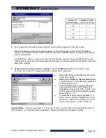
Number of
Thermocouples
Number of UUTs
Value to be Entered
1 - 16
2
1 - 32
4
1 - 48
6
1 - 64
8
8. Cycle power to the chamber but leave the UUT power supply plugged in to the 120 V outlet.
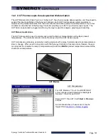
After the Synergy Controller boots up successfully, verify that the green LED on the UUT Module is
blinking. This indicates that data communications have been established between the Synergy Controller
and the UUT Module.
Important Note: When you have more than one UUT Module, verify that the green LED blinks on each
module. Each module is queried sequentially as the Synergy Controller gathers the temperature data from
each of the modules.
9.
Verify thermocouple temperature readings.
Press the
EVENTS
Navigation key on the Synergy
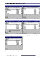
Controller. Open the UUT Temperature folder to display the screen below
♦
Remember that each UUT Module can accept
up to 16 T/C inputs.
♦
Each screen displays 8 sensors labeled Sensor
1 thru Sensor 8. You can view all 16 inputs of a
module with 2 screens.
♦
Press the
Next
button to view the next set of
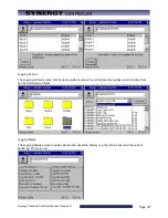
eight sensors for the first UUT Module. The
path display changes from UUT1 to UUT2. The
UUT2 screen will show the readings for actual
sensors No.’s 9 – 16.
♦
To view sensor inputs for UUT Modules. 2, 3
and 4, continue pressing the
Next
button. UUT
Module No. 2 data will be displayed by UUT3 /
UUT4, module by No. 3 UUT5 / UUT6, etc.
Important Note:
If your screen shows “x.x” for sensor “Temp”, go back to Step 7 and verify the Number of
UUTs entered. X.x indicates that the module isn’t being monitored by the Synergy Controller.
Содержание Synergy Compact
Страница 14: ...Synergy Controller Technical Manual Revision H Page 14 2 0 SPECIFICATIONS 2 1 Data Sheet...
Страница 71: ...Synergy Controller Technical Manual Revision H Page 71...
Страница 106: ...Synergy Controller Technical Manual Revision H Page 106...
Страница 123: ...Synergy Controller Technical Manual Revision H Page 123...
Страница 141: ...Synergy Controller Technical Manual Revision H Page 141 TE1151 6 Triac Output Board Schematic...
Страница 142: ...Synergy Controller Technical Manual Revision H Page 142 TE1708 6 Relay Board Schematic...
Страница 188: ...Synergy Controller Technical Manual Revision H Page 188...
Страница 274: ...Synergy Controller Technical Manual Revision H Page 274 Synergy Controller Step Syntax...
Страница 294: ...Synergy Controller Technical Manual Revision H Page 294...
Страница 312: ...Synergy Controller Technical Manual Revision H Page 312...
Страница 345: ...Synergy Controller Technical Manual Revision H Page 345...
Страница 346: ...Synergy Controller Technical Manual Revision H Page 346...

