Installing the Equipment
Page 2-2
Reference Guide: SM6610, SM6615, SM6620 and SM6625 Satellite Modulators
ST.RE.E10152.2
L-Band Output (Monitor) .............................2-15
2.5.7
S13450 DVB ASI & SPI Input Card
(Option) .......................................................2-15
Rear Panel View .........................................2-15
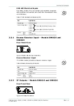
DVB ASI Electrical Inputs............................2-15
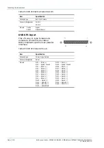
DVB SPI Input.............................................2-16
Powering Up/Down..................................................2-17
General .......................................................2-17
Powering Up................................................2-17
Powering Down...........................................2-17
List of Figures
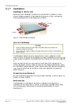
Figure 2.1: Air-flow Through the Equipment.................................. 2-4
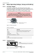
Figure 2.2: AC Power Inlet Assembly............................................ 2-6
Figure 2.3: Location of the Technical Earth................................... 2-6
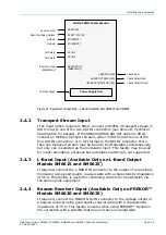
Figure 2.4: Equipment Connections – IF Output Models
SM6610 and SM6620 .................................................. 2-8
Figure 2.5: Equipment Connections – L-Band Output Models
SM6615 and SM6625 .................................................. 2-9
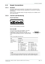
Figure 2.6: Control and Monitoring Connections......................... 2-11
Figure 2.7: DVB ASI Input Connections...................................... 2-12
Figure 2.8: Beacon Receiver Input Connections......................... 2-13
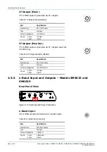
Figure 2.9: IF Output Connections .............................................. 2-13
Figure 2.10: L-Band Input and Output Connections.................... 2-14
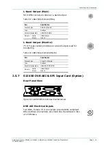
Figure 2.11: S13450 DVB ASI & SPI Input Card Connections ... 2-15
List of Tables
Table 2.1: Fuse Information .......................................................... 2-6
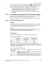
Table 2.2: Supply Cord Wiring Colours......................................... 2-7
Table 2.3: Non-standard Supply Cord Wire Colours..................... 2-7
Table 2.4: RS-232/485 Connector Pin-outs ................................ 2-11
Table 2.5: Reset/Status Connector Pin-outs............................... 2-12
Table 2.6: Ethernet Pin-outs (2 off) ............................................. 2-12
Table 2.7: DVB ASI Electrical Connectors (2 off)........................ 2-13
Table 2.8: Beacon Receiver Input Connector ............................. 2-13
Table 2.9: IF Output Connector (Main)........................................ 2-14
Table 2.10: IF Output Connector (Monitor) ................................. 2-14
Table 2.11: L-Band Input Connector ........................................... 2-14
Table 2.12: L-Band Output Connector (Main) ............................. 2-15
Table 2.13: L-Band Output Connector (Monitor)......................... 2-15
Table 2.14: DVB ASI Electrical Connectors (2 off)...................... 2-16
Table 2.15: DVB SPI Connector Pin-outs ................................... 2-16
Содержание SM6610
Страница 10: ...Introduction Page 1 2 Reference Guide SM6610 SM6615 SM6620 and SM6625 Satellite Modulators ST RE E10152 2 BLANK...
Страница 138: ...Equipment Description Page 7 2 Reference Guide SM6610 SM6615 SM6620 and SM6625 Satellite Modulators ST RE E10152 2 BLANK...
Страница 172: ...Licence Keys Page 10 2 Reference Guide SM6610 SM6615 SM6620 and SM6625 Satellite Modulators ST RE E10152 2 BLANK...

