Installing the Equipment
Reference Guide: SM6610, SM6615, SM6620 and SM6625 Satellite Modulators
Page 2-11
ST.RE.E10152.2
2.5 Signal
Connections
2.5.1 General
All signal input/output connectors are located at the rear panel of the
Modulator. For a detailed interface specification see Annex B, Technical
Specification.
Always use the specified cables for signal integrity and compliance with
EMC requirements.
2.5.2 Control
and
Monitoring
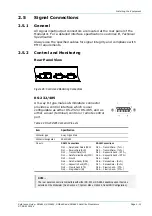
Rear Panel View
Figure 2.6: Control and Monitoring Connections
RS-232/485
A 9-way D-type male sub-miniature connector
provides a control interface which is user
configurable as either RS-232 or RS-485, and as
either a local (terminal) control or remote control
port.
Table 2.4: RS-232/485 Connector Pin-outs
Item Specification
Connector type
9-way D-type, Male
Connector designation
RS-232/485
Pin-outs
RS-232 Connections
Pin 1
Data Carrier Detect (DCD)
Pin 2
Receive Data (RxD)
Pin 3
Transmit Data (TxD)
Pin 4
Data Terminal Ready (DTR)
Pin 5
Ground
Pin 6
Data Set Ready (DSR)
Pin 7
Request to Send (RTS)
Pin 8
Clear to Send (CTS)
Pin 9
Ring Indicator (RI)
RS-485 Connections
Pin 1
Transmit Data
−
(TxD
−
)
Pin 2
Transmit Data
+
(TxD
+
)
Pin 3
Request to Send
−
(RTS
−
)
Pin 4
Request to Send
+
(RTS
+
)
Pin 5
Ground
Pin 6
Receive Data
−
(RxD
−
)
Pin 7
Receive Data
+
(RxD
+
)
Pin 8
Clear to Send
−
(CTS
−
)
Pin 9
Clear to Send
+
(CTS
+
)
NOTE…
The rear panel connector is compatible with either RS-232 or RS-485, depending upon the mode
selected on the Modulator. (See Section 3.7, System Menu, Option 4, Serial Port Configuration.)
Содержание SM6610
Страница 10: ...Introduction Page 1 2 Reference Guide SM6610 SM6615 SM6620 and SM6625 Satellite Modulators ST RE E10152 2 BLANK...
Страница 138: ...Equipment Description Page 7 2 Reference Guide SM6610 SM6615 SM6620 and SM6625 Satellite Modulators ST RE E10152 2 BLANK...
Страница 172: ...Licence Keys Page 10 2 Reference Guide SM6610 SM6615 SM6620 and SM6625 Satellite Modulators ST RE E10152 2 BLANK...

