Installing the Equipment
Page 2-10
Reference Guide: SM6610, SM6615, SM6620 and SM6625 Satellite Modulators
ST.RE.E10152.2
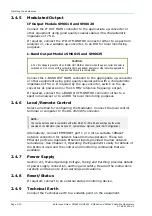
2.4.5 Modulated
Output
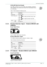
IF Output Models SM6610 and SM6620
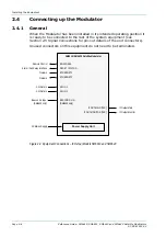
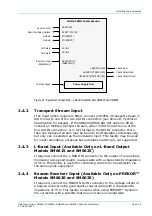
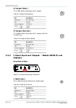
Connect the IF OUT MAIN connector to the appropriate up-converter or
other equipment using good quality coaxial cable with a characteristic
impedance of 75
Ω
.
If required, connect the IF OUT MONITOR connector either to a spectrum
analyser or, via a suitable up-converter, to an IRD for local monitoring
purposes.
L-Band Output Models SM6615 and SM6625
CAUTION…
A 24 V dc voltage is present at the L-BAND OUT MAIN connector when the up-converter dc power is
switched on. Do not connect this output directly to a spectrum analyser or other sensitive equipment.
The use of a dc block is recommended.
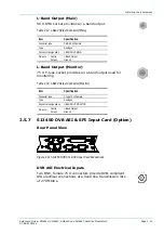
Connect the L-BAND OUT MAIN connector to the appropriate up-converter
or other equipment using good quality coaxial cable with a characteristic
impedance of 50
Ω
. If required by the up-converter, switch on the up-
converter dc power and/or the 10 MHz reference frequency output.
If required, connect the L-BAND OUT MONITOR connector either to a
spectrum analyser or to an IRD for local monitoring purposes.
2.4.6 Local/Remote
Control
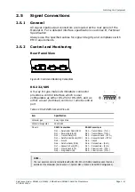
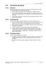
Select a method for configuring the Modulator. Connect the local control
terminal or computer to the RS-232/485 connector.
NOTE…
The rear panel connector is compatible with either RS-232 or RS-485, depending upon the mode
selected on the Modulator. (See Section 3.7, System Menu, Option 4, Serial Port Configuration.)
Alternatively, connect ETHERNET port 1 or 2 into a suitable 10BaseT
network connection for network based remote operation. These two
Ethernet ports are duplicate Ethernet inputs provided to allow network
redundancy. See Chapter 3, Operating the Equipment Locally for details of
the protocol used and the control and monitoring commands that are
available.
2.4.7 Power
Supply
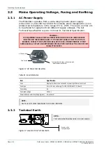
Section 2.3, Mains Operating Voltage, Fusing and Earthing provides details
of power supply connection, earthing and safety. Read all the instructions
carefully and take note of all warnings and cautions.
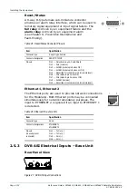
2.4.8 Reset/Status
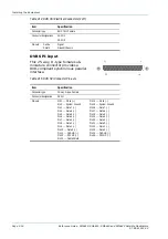
If required, connect to an external status monitoring device.
2.4.9 Technical
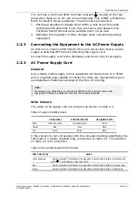
Earth
Connect the Technical earth to a suitable point on the equipment.
Содержание SM6610
Страница 10: ...Introduction Page 1 2 Reference Guide SM6610 SM6615 SM6620 and SM6625 Satellite Modulators ST RE E10152 2 BLANK...
Страница 138: ...Equipment Description Page 7 2 Reference Guide SM6610 SM6615 SM6620 and SM6625 Satellite Modulators ST RE E10152 2 BLANK...
Страница 172: ...Licence Keys Page 10 2 Reference Guide SM6610 SM6615 SM6620 and SM6625 Satellite Modulators ST RE E10152 2 BLANK...

