Reference Guide: SM6610, SM6615, SM6620 and SM6625 Satellite Modulators
Page 8-1
ST.RE.E10152.2
Chapter 8
8.
Preventive Maintenance and
Fault-finding
Contents
Introduction ............................................................... 8-3
Routine Checks......................................................... 8-3
Cooling Fans ................................................ 8-3
Cleaning ....................................................... 8-3
Servicing ................................................................... 8-3
Conditions Requiring Servicing..................... 8-3
Replacement Parts ....................................... 8-4
Checks on Completion of Servicing.............. 8-4
Maintenance and Support Services .......................... 8-4
Introduction................................................... 8-4
Warranty ....................................................... 8-4
8.4.3
Levels of Continuing TANDBERG
Television Service Support........................... 8-4
Maintenance Philosophy............................... 8-5
Fault Diagnosis for an Operator ................... 8-5
Boot Errors................................................................ 8-6
Boot Display ................................................. 8-6
Self-test Result Messages............................ 8-6
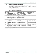
Poor Error Performance............................................ 8-7
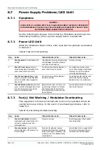
Power Supply Problems/LED Unlit............................ 8-8
Symptoms..................................................... 8-8
Power LED Unlit ........................................... 8-8
8.7.3
Fan(s) Not Working / Modulator
Overheating .................................................. 8-8
VT100 Terminal Emulation Program Problems......... 8-9
Alarm and Failure Reporting ..................................... 8-9
Introduction................................................... 8-9
Alarm Severity Levels ...................................8-9
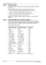
Alarm Groups..............................................8-10
Host Controller Card (Slot 3) Alarms ..........8-10
Input Card (Slot 4) Alarms ..........................8-11
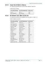
Baseband Card (Slot 2) Alarms ..................8-11
IF Card (Slot 1) Alarms ...............................8-12
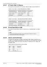
Front Panel Alarm LED ...............................8-12
Alarm and Fail Relays.................................8-12
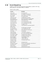
Event Reporting.......................................................8-13
List of Figures
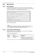
Figure 8.1: Example Boot Display ................................................. 8-6
List of Tables
Table 8.1: Self-test Results Messages .......................................... 8-6
Table 8.2: Poor Error Performance Fault-finding........................... 8-7
Table 8.3: Power LED Unlit Fault-finding....................................... 8-8
Table 8.4: Fans Not Working / Modulator Overheating ................. 8-8
Table 8.5: Host Controller Card Alarms....................................... 8-10
Table 8.6: Input Card Alarms....................................................... 8-11
Table 8.7: Baseband Card Alarms............................................... 8-11
Table 8.8: IF Card Alarms – IF Output Models SM6610 and
SM6620...................................................................... 8-12
Table 8.9: IF Card Alarms – L-Band Output Models SM6615
and SM6625............................................................... 8-12
Table 8.10: Effect of Masking the Alarm and Fail Conditions...... 8-12
Table 8.11: Event Log Entries ..................................................... 8-13
Содержание SM6610
Страница 10: ...Introduction Page 1 2 Reference Guide SM6610 SM6615 SM6620 and SM6625 Satellite Modulators ST RE E10152 2 BLANK...
Страница 138: ...Equipment Description Page 7 2 Reference Guide SM6610 SM6615 SM6620 and SM6625 Satellite Modulators ST RE E10152 2 BLANK...
Страница 172: ...Licence Keys Page 10 2 Reference Guide SM6610 SM6615 SM6620 and SM6625 Satellite Modulators ST RE E10152 2 BLANK...

