Installing the Equipment
Page 2-8
Reference Guide: SM6610, SM6615, SM6620 and SM6625 Satellite Modulators
ST.RE.E10152.2
2.4
Connecting up the Modulator
2.4.1 General
When the Modulator has been installed in its intended operating position it
is ready to be connected to the rest of the system equipment (see
Section 2.5 Signal Connections for pin-out details of the unit connectors).
Unused connectors on this equipment do not need to be terminated.
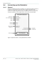
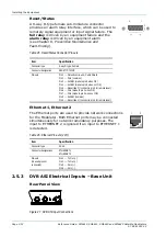
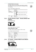
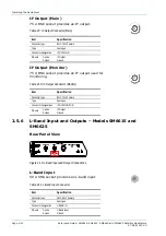
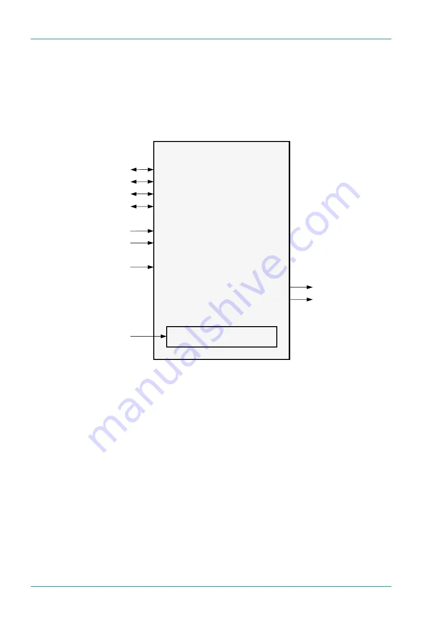
Figure 2.4: Equipment Connections – IF Output Models SM6610 and SM6620
SM6610 / SM6620 Satellite Modulator
RS-232/485
RESET / STATUS
ETHERNET 1
ETHERNET 2
ASI IN 1
ASI IN 2
BEACON Rx IN
(SM6620 only)
IF OUT MAIN (75R)
IF OUT MONITOR (75R)
Remote Control
Alarm / Fail Relay Interface
Network
Network
ASI Data In
ASI Data In
Beacon Rx Input
(SM6620 only)
AC Mains Supply
Power Supply Unit
IF Output Main
IF Output Monitor
Содержание SM6610
Страница 10: ...Introduction Page 1 2 Reference Guide SM6610 SM6615 SM6620 and SM6625 Satellite Modulators ST RE E10152 2 BLANK...
Страница 138: ...Equipment Description Page 7 2 Reference Guide SM6610 SM6615 SM6620 and SM6625 Satellite Modulators ST RE E10152 2 BLANK...
Страница 172: ...Licence Keys Page 10 2 Reference Guide SM6610 SM6615 SM6620 and SM6625 Satellite Modulators ST RE E10152 2 BLANK...

