
Technical Instructions
LMV Series
Document No. LV5-1000
Section 2
Page 4 SCC Inc.
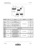
CANbus (continued)
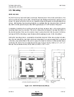
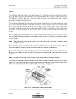
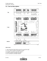
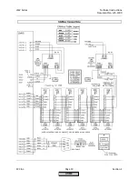
The shield of the CANbus cable must be connected on each cable segment (between the LMV5 and the
actuators or PLL52 module) so that the entire shield has continuity with terminal X51.1 which is the
shield connection on the LMV5. This is achieved by clamping the shield on both cable segments with the
metal clamps provided on the cable entry of each actuator. Clamps for the CANbus shield are also
provided on the PLL52 module.
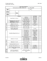
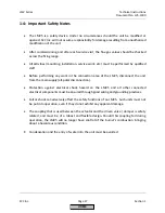
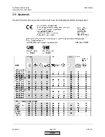
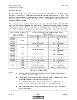
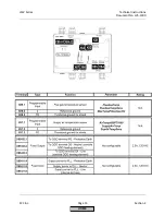
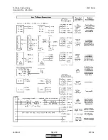
The current provided by one AGG5.210 transformer is usually sufficient to meet the demands of the
LMV5 base unit, AZL5 and actuators on a typical burner / boiler without a PLL52 module. However,
situations occur when one AGG5.210 transformer is not sufficient, and a second transformer must be
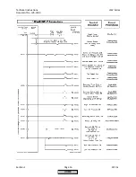
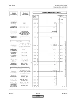
used. The figure below outlines the number of transformers that should be used for different situations.
Number and type of actuators
wired on the CANbus
moving concurrently
.
Permissible total CANbus cable length including AZL5 (feet).
Single Transformer
Actuators at
100%
rated torque.
Actuators at
80%
rated torque.
2 SQM45
0 SQM48
115
125
3 SQM45
85
95
4 SQM45
70
80
5 SQM45
2nd Transformer Req.
2nd Transformer Req.
1 SQM45
1 SQM48
85
95
2 SQM45
70
80
3 SQM45
2nd Transformer Req.
30
4 SQM45
2nd Transformer Req.
1 SQM45
2 SQM48
2nd Transformer Req.
30
2 SQM45
2nd Transformer Req.
3 SQM45
1 SQM45
3 SQM48
2nd Transformer Req.
2nd Transformer Req.
2 SQM45
1 SQM45
4 SQM48
2nd & 3rd Transformer Req.
2nd Transformer Req.
0 SQM45
2 SQM48
58
70
3 SQM48
2nd Transformer Req.
2nd Transformer Req.
4 SQM48
5 SQM48
2nd & 3rd Transformer Req.
2nd & 3rd Transformer Req.
Figure 2-1.4: CANbus Loading
Notes:
•
When two transformers are used, the loading should be divided between the two
transformers as equally as possible.
•
The second transformer should be placed as close as possible to the actuators / PLL52
module that it powers due to voltage drop considerations.
•
When adding a PLL52 module, subtract 20 ft from the cable length on the chart.
•
Absolute maximum cable length is 300 ft (CANbus communication limitation).
•
Never connect the 12VAC1 / 12VAC2 from one transformer to 12VAC1 / 12VAC2 on
any other transformer.
HOME
Содержание LMV 5 Series
Страница 2: ...Intentionally Left Blank ...
Страница 25: ...LMV Series Technical Instructions Document No LV5 1000 SCC Inc Page 21 Section 1 Intentionally Left Blank HOME ...
Страница 27: ...LMV Series Technical Instructions Document No LV5 1000 SCC Inc Page 23 Section 1 Intentionally Left Blank HOME ...
Страница 41: ...LMV Series Technical Instructions Document No LV5 1000 SCC Inc Page 7 Section 2 HOME ...
Страница 42: ...Technical Instructions LMV Series Document No LV5 1000 Section 2 Page 8 SCC Inc HOME ...
Страница 43: ...LMV Series Technical Instructions Document No LV5 1000 SCC Inc Page 9 Section 2 HOME ...
Страница 44: ...Technical Instructions LMV Series Document No LV5 1000 Section 2 Page 10 SCC Inc HOME ...
Страница 45: ...LMV Series Technical Instructions Document No LV5 1000 SCC Inc Page 11 Section 2 HOME ...
Страница 46: ...Technical Instructions LMV Series Document No LV5 1000 Section 2 Page 12 SCC Inc HOME ...
Страница 47: ...LMV Series Technical Instructions Document No LV5 1000 SCC Inc Page 13 Section 2 HOME ...
Страница 48: ...Technical Instructions LMV Series Document No LV5 1000 Section 2 Page 14 SCC Inc HOME ...
Страница 49: ...LMV Series Technical Instructions Document No LV5 1000 SCC Inc Page 15 Section 2 HOME ...
Страница 50: ...Technical Instructions LMV Series Document No LV5 1000 Section 2 Page 16 SCC Inc HOME ...
Страница 51: ...LMV Series Technical Instructions Document No LV5 1000 SCC Inc Page 17 Section 2 HOME ...
Страница 52: ...Technical Instructions LMV Series Document No LV5 1000 Section 2 Page 18 SCC Inc HOME ...
Страница 53: ...LMV Series Technical Instructions Document No LV5 1000 SCC Inc Page 19 Section 2 HOME ...
Страница 54: ...Technical Instructions LMV Series Document No LV5 1000 Section 2 Page 20 SCC Inc HOME ...
Страница 55: ...LMV Series Technical Instructions Document No LV5 1000 SCC Inc Page 21 Section 2 HOME ...
Страница 56: ...Technical Instructions LMV Series Document No LV5 1000 Section 2 Page 22 SCC Inc Intentionally Left Blank HOME ...
Страница 116: ...Technical Instructions LMV Series Document No LV5 1000 Section 3 Page 58 SCC Inc Intentionally Left Blank HOME ...
Страница 150: ...Technical Instructions LMV Series Document No LV5 1000 Section 4 Page 32 SCC Inc Intentionally Left Blank HOME ...
Страница 170: ...Technical Instructions LMV Series Document No LV5 1000 Section 5 Page 18 SCC Inc Intentionally Left Blank HOME ...
Страница 290: ...Technical Instructions LMV Series Document No LV5 1000 Section 8 Page 20 SCC Inc Intentionally Left Blank HOME ...
Страница 306: ...Technical Instructions LMV Series Document No LV5 1000 Section 9 Page 14 SCC Inc Intentionally Left Blank HOME ...
Страница 373: ...Intentionally Left Blank ...