
LMV
Series
Technical
Instructions
Document
No.
LV5
‐
1000
SCC
Inc.
Page
17
Section
4
Suggested
Ratio
Control
Curve
Commissioning
1.
The
procedure
below
assumes
the
following:
a.
Pre
‐
requisites
for
Basic
LMV51
systems
or
LMV52
systems
(from
above)
are
met.
b.
Procedure
for
Configuring
(Parameterization
of)
an
LMV5
has
been
done
(from
above).
c.
This
is
a
first
‐
time
commissioning
of
the
LMV5
and
the
combustion
control
curve
is
blank
(no
points
entered).
d.
The
burner
has
been
lit
off,
and
is
at
ignition
position.
e.
A
calibrated
stack
gas
analyzer
is
sampling
the
stack
gas
and
can
read
%O
2
and
ppm
CO.
f.
The
boiler
has
been
warmed
up
to
operating
temperature
/
pressure.
2.
If
activated,
set
parameter
ProgramStop
to
deactivated.
This
will
permit
the
ratio
control
curve
to
be
commissioned.
The
ratio
control
curve
can
be
found
under
the
menu:
Params
&
Display
>
RatioControl
>
GasSettings
>
CurveParams
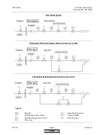
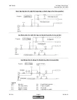
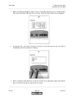
3.
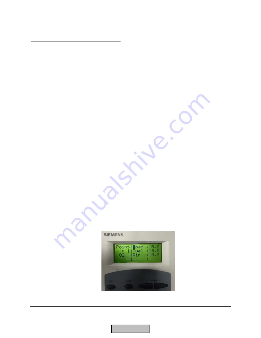
Go
to
Point
1.
Point
1
is
automatically
set
to
ignition
position
values.
When
Point
1
is
entered,
the
AZL
will
prompt
to
“change”
or
“delete”
the
point.
“Change”
should
be
selected.
Next,
the
AZL
will
prompt
for
“Followed”
or
“Not
followed”.
“Followed”
should
be
selected.
All
actuators
and
/
or
VSD
that
have
been
activated
should
show
up
on
this
screen.
If
more
than
one
Aux
actuator
or
VSD
are
activated,
the
screen
may
need
to
be
scrolled
down
to
show
the
other
actuators.
If
an
O
2
sensor
is
being
used
and
is
activated,
the
O
2
reading
will
also
be
displayed.
NOTE:
Using
the
“Not
followed”
option
is
possible
but
not
recommended
for
most
situations
since
the
results
of
changing
the
actuator
positions
in
“Not
followed”
mode
cannot
be
seen
real
time
on
a
combustion
analyzer.
When
“Followed”
is
selected,
a
carat
(>)
is
shown
when
the
actuators
/
VSD
are
moving
to
the
displayed
position.
A
colon
(:)
is
shown
when
the
indicated
positions
are
reached.
A
pound
(#)
is
shown
when
the
Aux
3
FGR
actuator
is
being
held
at
position
due
to
a
time
or
temperature
‐
based
FGR
hold.
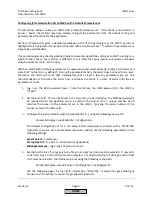
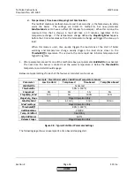
4.
If
the
low
fire
point
is
not
known
(maximum
burner
turndown),
adjust
the
Point
1
actuator
positions
until
maximum
safe
burner
turndown
is
achieved.
Record
the
fuel
flow.
If
the
fuel
flow
is
not
available,
burner
head
pressure
can
be
used
as
a
last
resort.
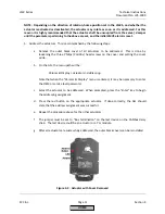
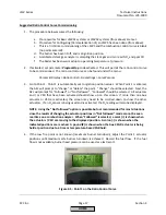
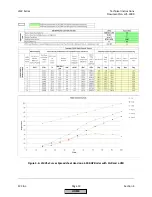
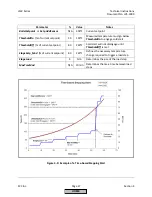
Figure
4
‐
5:
Point
1
on
the
Ratio
Control
Curve
HOME
Содержание LMV 5 Series
Страница 2: ...Intentionally Left Blank ...
Страница 25: ...LMV Series Technical Instructions Document No LV5 1000 SCC Inc Page 21 Section 1 Intentionally Left Blank HOME ...
Страница 27: ...LMV Series Technical Instructions Document No LV5 1000 SCC Inc Page 23 Section 1 Intentionally Left Blank HOME ...
Страница 41: ...LMV Series Technical Instructions Document No LV5 1000 SCC Inc Page 7 Section 2 HOME ...
Страница 42: ...Technical Instructions LMV Series Document No LV5 1000 Section 2 Page 8 SCC Inc HOME ...
Страница 43: ...LMV Series Technical Instructions Document No LV5 1000 SCC Inc Page 9 Section 2 HOME ...
Страница 44: ...Technical Instructions LMV Series Document No LV5 1000 Section 2 Page 10 SCC Inc HOME ...
Страница 45: ...LMV Series Technical Instructions Document No LV5 1000 SCC Inc Page 11 Section 2 HOME ...
Страница 46: ...Technical Instructions LMV Series Document No LV5 1000 Section 2 Page 12 SCC Inc HOME ...
Страница 47: ...LMV Series Technical Instructions Document No LV5 1000 SCC Inc Page 13 Section 2 HOME ...
Страница 48: ...Technical Instructions LMV Series Document No LV5 1000 Section 2 Page 14 SCC Inc HOME ...
Страница 49: ...LMV Series Technical Instructions Document No LV5 1000 SCC Inc Page 15 Section 2 HOME ...
Страница 50: ...Technical Instructions LMV Series Document No LV5 1000 Section 2 Page 16 SCC Inc HOME ...
Страница 51: ...LMV Series Technical Instructions Document No LV5 1000 SCC Inc Page 17 Section 2 HOME ...
Страница 52: ...Technical Instructions LMV Series Document No LV5 1000 Section 2 Page 18 SCC Inc HOME ...
Страница 53: ...LMV Series Technical Instructions Document No LV5 1000 SCC Inc Page 19 Section 2 HOME ...
Страница 54: ...Technical Instructions LMV Series Document No LV5 1000 Section 2 Page 20 SCC Inc HOME ...
Страница 55: ...LMV Series Technical Instructions Document No LV5 1000 SCC Inc Page 21 Section 2 HOME ...
Страница 56: ...Technical Instructions LMV Series Document No LV5 1000 Section 2 Page 22 SCC Inc Intentionally Left Blank HOME ...
Страница 116: ...Technical Instructions LMV Series Document No LV5 1000 Section 3 Page 58 SCC Inc Intentionally Left Blank HOME ...
Страница 150: ...Technical Instructions LMV Series Document No LV5 1000 Section 4 Page 32 SCC Inc Intentionally Left Blank HOME ...
Страница 170: ...Technical Instructions LMV Series Document No LV5 1000 Section 5 Page 18 SCC Inc Intentionally Left Blank HOME ...
Страница 290: ...Technical Instructions LMV Series Document No LV5 1000 Section 8 Page 20 SCC Inc Intentionally Left Blank HOME ...
Страница 306: ...Technical Instructions LMV Series Document No LV5 1000 Section 9 Page 14 SCC Inc Intentionally Left Blank HOME ...
Страница 373: ...Intentionally Left Blank ...