
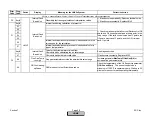

Error
Code
Diag.
Code
Device
Display
Meaning for the LMV5x System
Corrective Action
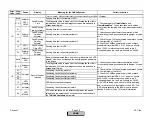
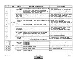
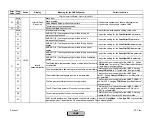
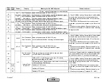
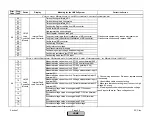
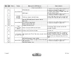
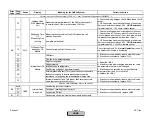
17
Page too long open
18
Page disrupted
19
Invalid parameter access
1B
Fault during copying of parameter page
1E
External plausibility fault. This type of fault covers possible
faults occurring due to invalid presettings in the drive
commands. In response, the presettings will be ignored
1) Check the paramters related to special positions.
The special positions of each activated actuator should
be programmed between 0 and 90 degrees.
1F
Internal plausibility fault. This type of fault covers possible
faults that can occur due to strong electrical noise
1) If fault occurs sporadically: Reduce electrical noise.
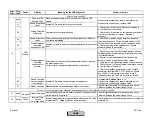
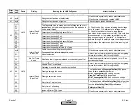
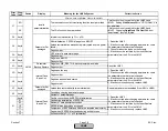
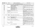
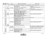
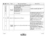
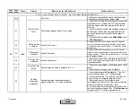
A2
A3
A4
A5
Any #
-
Internal load controller has detected a fault. Type of fault: See
diagnostic code
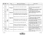
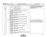
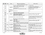
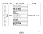
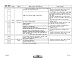
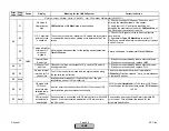
10
No actual Value
Slope at End of
Identification
-
12
Invalid XP identified
13
Invalid TN identified
14
TU longer than identification time
15
Invalid TV identified
16
Timeout with
Adaption
Timeout during observation time
PV (Process Varible) is not changing in response to
firing rate during the adaption time. Adaption times out
due to lack of change in the measured PV. Check
sensor and thermal system.
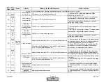
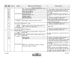
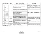
17
Cold Start thermal
Shock Protection
active
A warning indicating that the Cold Start Thermal Shock
Protection (CSTP) is activated
This can be deactivated, if desired. See parameters
concerning the load controller in the settings section.
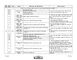
18
Timeout with
Adaption
Timeout during delivery of adaption rate and while process is
being watched
PV (Process Varible) is not changing in response to
firing rate during the adaption time. Adaption times out
due to lack of change in the measured PV. Check
sensor and thermal system.
22
Setpoint Temp
Controller above
maximum Limit
The current setpoint (W1, W2, W3) is above the value of the
internal temperature limiter.
Raise the value of the internal temperaure limiter or
decrease the current setpoint.
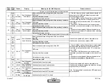
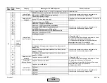
See diagnostic codes for A1 error codes. These diagnostic codes are identical, except they apply to the Gas (Oil) Actuator.
See diagnostic codes for A1 error codes. These diagnostic codes are identical, except they apply to the Auxiliary 2 Actuator.
Fault with Base Unit (LMV5) Internal Load Controller
1) Reset the LMV5
2) If fault occurred after changing a parameter, check
the parameters that were last changed.
3) If fault cannot be rectified by the reset: Restore
parameters form the AZL to the LMV5
4) If fault occurs continuously, replace LMV5.
A1
If fault occurs sporadically, reduce electrical noise.
If fault occurs continuously, replace LMV5.
A6
LMV5
Load
Controller
Module
See diagnostic codes for A1 error codes. These diagnostic codes are identical, except they apply to the Oil Actuator.
See diagnostic codes for A1 error codes. These diagnostic codes are identical, except they apply to the Auxiliary 1 Actuator.
Adaption invalid
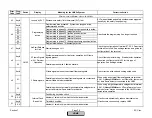
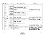
Fault with Connected Actuators
Internal Fault Air
Actuator
Air
Actuator
Section 7
Page 43
SCC Inc.
HOME
HOME
Содержание LMV 5 Series
Страница 2: ...Intentionally Left Blank ...
Страница 25: ...LMV Series Technical Instructions Document No LV5 1000 SCC Inc Page 21 Section 1 Intentionally Left Blank HOME ...
Страница 27: ...LMV Series Technical Instructions Document No LV5 1000 SCC Inc Page 23 Section 1 Intentionally Left Blank HOME ...
Страница 41: ...LMV Series Technical Instructions Document No LV5 1000 SCC Inc Page 7 Section 2 HOME ...
Страница 42: ...Technical Instructions LMV Series Document No LV5 1000 Section 2 Page 8 SCC Inc HOME ...
Страница 43: ...LMV Series Technical Instructions Document No LV5 1000 SCC Inc Page 9 Section 2 HOME ...
Страница 44: ...Technical Instructions LMV Series Document No LV5 1000 Section 2 Page 10 SCC Inc HOME ...
Страница 45: ...LMV Series Technical Instructions Document No LV5 1000 SCC Inc Page 11 Section 2 HOME ...
Страница 46: ...Technical Instructions LMV Series Document No LV5 1000 Section 2 Page 12 SCC Inc HOME ...
Страница 47: ...LMV Series Technical Instructions Document No LV5 1000 SCC Inc Page 13 Section 2 HOME ...
Страница 48: ...Technical Instructions LMV Series Document No LV5 1000 Section 2 Page 14 SCC Inc HOME ...
Страница 49: ...LMV Series Technical Instructions Document No LV5 1000 SCC Inc Page 15 Section 2 HOME ...
Страница 50: ...Technical Instructions LMV Series Document No LV5 1000 Section 2 Page 16 SCC Inc HOME ...
Страница 51: ...LMV Series Technical Instructions Document No LV5 1000 SCC Inc Page 17 Section 2 HOME ...
Страница 52: ...Technical Instructions LMV Series Document No LV5 1000 Section 2 Page 18 SCC Inc HOME ...
Страница 53: ...LMV Series Technical Instructions Document No LV5 1000 SCC Inc Page 19 Section 2 HOME ...
Страница 54: ...Technical Instructions LMV Series Document No LV5 1000 Section 2 Page 20 SCC Inc HOME ...
Страница 55: ...LMV Series Technical Instructions Document No LV5 1000 SCC Inc Page 21 Section 2 HOME ...
Страница 56: ...Technical Instructions LMV Series Document No LV5 1000 Section 2 Page 22 SCC Inc Intentionally Left Blank HOME ...
Страница 116: ...Technical Instructions LMV Series Document No LV5 1000 Section 3 Page 58 SCC Inc Intentionally Left Blank HOME ...
Страница 150: ...Technical Instructions LMV Series Document No LV5 1000 Section 4 Page 32 SCC Inc Intentionally Left Blank HOME ...
Страница 170: ...Technical Instructions LMV Series Document No LV5 1000 Section 5 Page 18 SCC Inc Intentionally Left Blank HOME ...
Страница 290: ...Technical Instructions LMV Series Document No LV5 1000 Section 8 Page 20 SCC Inc Intentionally Left Blank HOME ...
Страница 306: ...Technical Instructions LMV Series Document No LV5 1000 Section 9 Page 14 SCC Inc Intentionally Left Blank HOME ...
Страница 373: ...Intentionally Left Blank ...