

LMV Series
Technical Instructions
Document No. LV5-8000
SCC Inc.
Page 21
Appendix A
Pilot Valve Proving (continued)
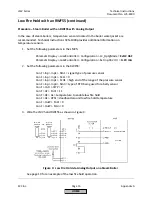
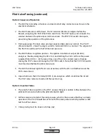
3.
The times for each of the four stages of valve proving need to be set. To do so, use the
following menu paths in the LMV5:
Params & Display > BurnerControl > ValveProving > VP_EvacTme
Params & Display > BurnerControl > ValveProving > VP_TmeAtmPress
Params & Display > BurnerControl > ValveProving > VP_FillTme
Params & Display > BurnerControl > ValveProving > VP_Tme_GasPress
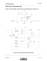
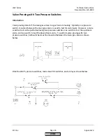
“VP_EvacTme” is the time that the downstream valve is energized in order to evacuate
the chamber between the upstream and downstream valves (phase 80). This is typically
set to 3 seconds, but should not be set any less than the opening time of the valves.
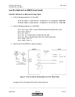
“VP_FillTme” is the time that the upstream valve is energized in order to pressurize the
chamber between the upstream and downstream valves (phase 82). This is typically set
to 3 seconds, but should not be set any less than the opening time of the valves.
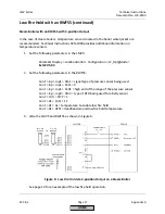
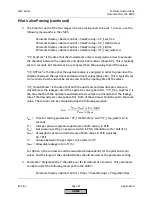
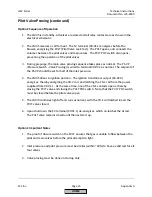
“VP_TmeAtmPress” is the time that both the upstream and downstream valves are
closed to test the leakage rate of the upstream valve (phase 81). “VP_Tme_GasPress” is
the time that both the upstream and downstream valves are closed to test the leakage
rate of the downstream valve (phase 83). Both of these times should be set to the same
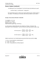
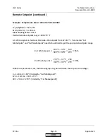
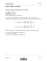
value. These times can be calculated using the following equation:
௧௦௧
=
−
௦௧
×
× 3600
௧
×
t
test
= Time for setting parameters “VP_TmeAtmPress” and “VP_Tme_GasPress” in
seconds
P
i
=
Inlet gas pressure (pressure upstream of both valves) in PSIG
P
set
= Gas pressure setting on pressure switch in PSIG (should be set for half of P
i
)
P
atm
= Atmospheric pressure downstream of both valves in PSIA (typically
14.7 PSI)
V =
Volume between the gas valves to be tested in ft
3
Q
leak
= Allowable leakage rate in ft
3
/hr
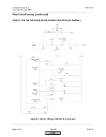
For Option 3, these times should be calculated independently for the pilot and main
valves, and the larger of the calculated times should be used as the parameter setting.
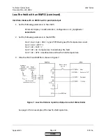
4.
Parameter “PreIgnitionTGas” should be set for its default of 2 seconds. This parameter
can be found at the following menu path in the LMV5:
Params & Display > BurnerControl > Times > TimesStartup1 > PreIgnitionTGas
HOME
Содержание LMV 5 Series
Страница 2: ...Intentionally Left Blank ...
Страница 25: ...LMV Series Technical Instructions Document No LV5 1000 SCC Inc Page 21 Section 1 Intentionally Left Blank HOME ...
Страница 27: ...LMV Series Technical Instructions Document No LV5 1000 SCC Inc Page 23 Section 1 Intentionally Left Blank HOME ...
Страница 41: ...LMV Series Technical Instructions Document No LV5 1000 SCC Inc Page 7 Section 2 HOME ...
Страница 42: ...Technical Instructions LMV Series Document No LV5 1000 Section 2 Page 8 SCC Inc HOME ...
Страница 43: ...LMV Series Technical Instructions Document No LV5 1000 SCC Inc Page 9 Section 2 HOME ...
Страница 44: ...Technical Instructions LMV Series Document No LV5 1000 Section 2 Page 10 SCC Inc HOME ...
Страница 45: ...LMV Series Technical Instructions Document No LV5 1000 SCC Inc Page 11 Section 2 HOME ...
Страница 46: ...Technical Instructions LMV Series Document No LV5 1000 Section 2 Page 12 SCC Inc HOME ...
Страница 47: ...LMV Series Technical Instructions Document No LV5 1000 SCC Inc Page 13 Section 2 HOME ...
Страница 48: ...Technical Instructions LMV Series Document No LV5 1000 Section 2 Page 14 SCC Inc HOME ...
Страница 49: ...LMV Series Technical Instructions Document No LV5 1000 SCC Inc Page 15 Section 2 HOME ...
Страница 50: ...Technical Instructions LMV Series Document No LV5 1000 Section 2 Page 16 SCC Inc HOME ...
Страница 51: ...LMV Series Technical Instructions Document No LV5 1000 SCC Inc Page 17 Section 2 HOME ...
Страница 52: ...Technical Instructions LMV Series Document No LV5 1000 Section 2 Page 18 SCC Inc HOME ...
Страница 53: ...LMV Series Technical Instructions Document No LV5 1000 SCC Inc Page 19 Section 2 HOME ...
Страница 54: ...Technical Instructions LMV Series Document No LV5 1000 Section 2 Page 20 SCC Inc HOME ...
Страница 55: ...LMV Series Technical Instructions Document No LV5 1000 SCC Inc Page 21 Section 2 HOME ...
Страница 56: ...Technical Instructions LMV Series Document No LV5 1000 Section 2 Page 22 SCC Inc Intentionally Left Blank HOME ...
Страница 116: ...Technical Instructions LMV Series Document No LV5 1000 Section 3 Page 58 SCC Inc Intentionally Left Blank HOME ...
Страница 150: ...Technical Instructions LMV Series Document No LV5 1000 Section 4 Page 32 SCC Inc Intentionally Left Blank HOME ...
Страница 170: ...Technical Instructions LMV Series Document No LV5 1000 Section 5 Page 18 SCC Inc Intentionally Left Blank HOME ...
Страница 290: ...Technical Instructions LMV Series Document No LV5 1000 Section 8 Page 20 SCC Inc Intentionally Left Blank HOME ...
Страница 306: ...Technical Instructions LMV Series Document No LV5 1000 Section 9 Page 14 SCC Inc Intentionally Left Blank HOME ...
Страница 373: ...Intentionally Left Blank ...