


LMV Series
Technical Instructions
Document No. LV5-1000
SCC Inc.
Page 3
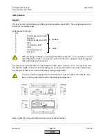
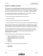
Section 9
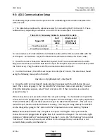
9-3: AZL5 Communication Setup
The following steps summarize the procedure for establishing communication between the
AZL5 and a PC.
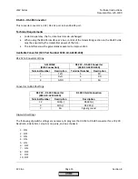
1.
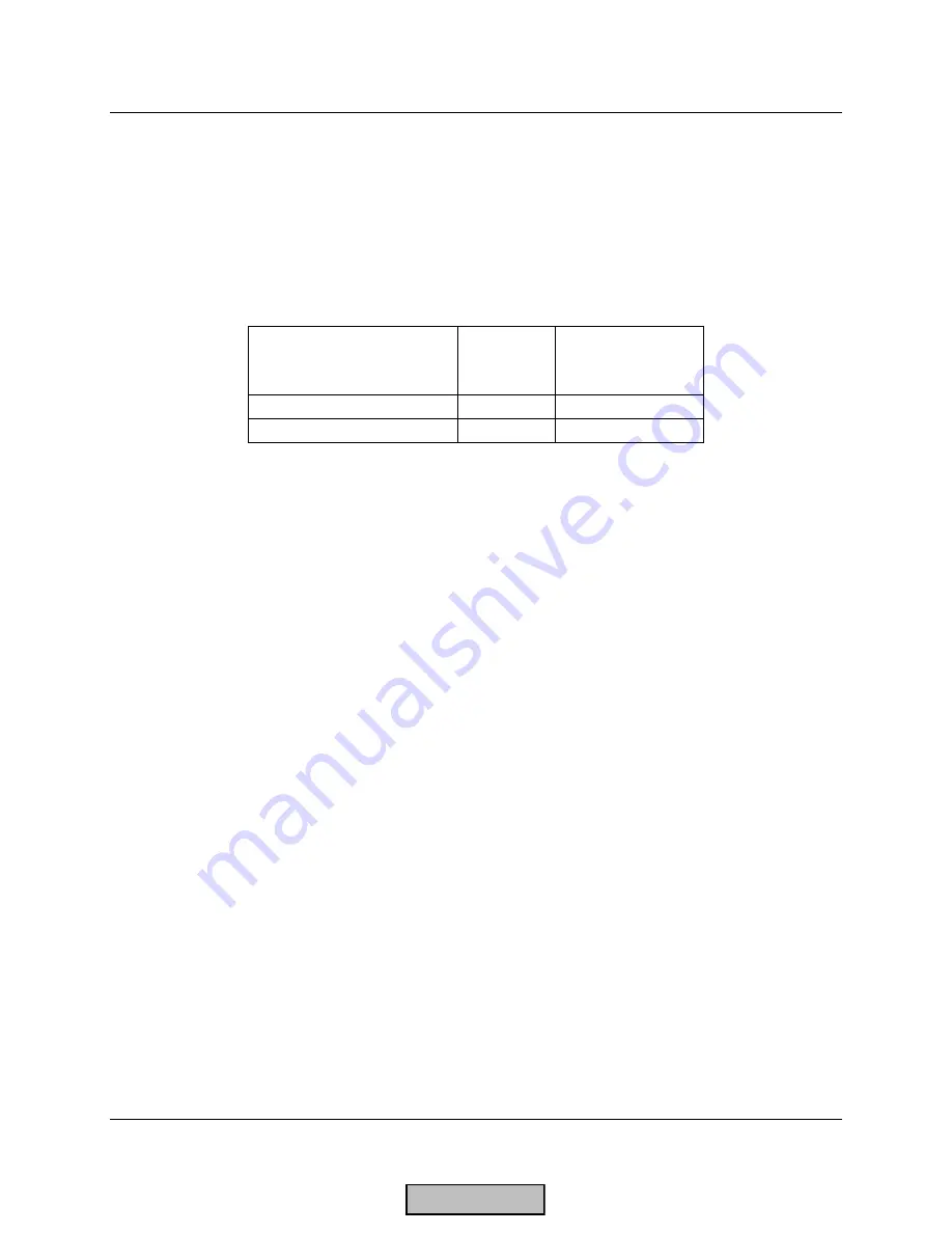
The table below outlines the cables necessary for connecting the PC to the AZL5. These
cables will vary depending on whether or not the PC has a serial port to connect to.
Table 9-3.1: Necessary Cables to Connect PC to AZL5
Type of PC
Null
modem
cable
USB-to-serial
converter w/
FTDI chipset
PC with serial port
X
PC without serial port
X
X
For convenience, SCC stocks both the null modem cable and the USB-to-serial cable with the
FTDI chipset. See Section 1 for part numbers and technical information for these cables.
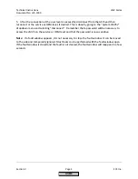
2.
Once the correct connection cables are acquired, the PC can be connected to the AZL5.
Plug one end of the connection cable into the 9-pin RS-232 port on the front of the AZL5 (under
the front cover). Plug the other end of the connection cable into the PC.
3.
In order to connect, the AZL5 must be put into
InterfacePC
mode. This selection is found
using the following menu path in the AZL5:
Operation > OptgModeSelect > InterfacePC
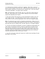
4.
Once the AZL5 is in
InterfacePC
mode, attempt to connect with the ACS450 on the user
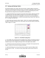
level. This is done by going to the “System LMV5x” dropdown menu and selecting “Connect”.
When the dialog box appears, select “User” and press OK. If the connection is successful,
proceed to step 5.
If the connection is not successful, check the com port settings. To check which com port the
connection cord is plugged into, open the computer’s Device Manager. Once open, expand the
“Ports (COM & LPT)” tab and check which com port is called “USB Serial Port”. This port must
match the port that the ACS450 software is reading. The com port being read by the ACS450
can be changed by going to the “System LMV5x”
dropdown menu and selecting
“Options”.
Note:
The ACS450 software only recognizes com ports 1 through 8. If the port that the
connection cord is plugged into is higher than 8, it needs to be changed. This is done by right-
clicking on “USB Serial Port” and selecting “Properties”. Go to the “Port Settings” tab and click
“Advanced”. From here, the com port number can be changed to any number that is not
currently being used by another device.
HOME
Содержание LMV 5 Series
Страница 2: ...Intentionally Left Blank ...
Страница 25: ...LMV Series Technical Instructions Document No LV5 1000 SCC Inc Page 21 Section 1 Intentionally Left Blank HOME ...
Страница 27: ...LMV Series Technical Instructions Document No LV5 1000 SCC Inc Page 23 Section 1 Intentionally Left Blank HOME ...
Страница 41: ...LMV Series Technical Instructions Document No LV5 1000 SCC Inc Page 7 Section 2 HOME ...
Страница 42: ...Technical Instructions LMV Series Document No LV5 1000 Section 2 Page 8 SCC Inc HOME ...
Страница 43: ...LMV Series Technical Instructions Document No LV5 1000 SCC Inc Page 9 Section 2 HOME ...
Страница 44: ...Technical Instructions LMV Series Document No LV5 1000 Section 2 Page 10 SCC Inc HOME ...
Страница 45: ...LMV Series Technical Instructions Document No LV5 1000 SCC Inc Page 11 Section 2 HOME ...
Страница 46: ...Technical Instructions LMV Series Document No LV5 1000 Section 2 Page 12 SCC Inc HOME ...
Страница 47: ...LMV Series Technical Instructions Document No LV5 1000 SCC Inc Page 13 Section 2 HOME ...
Страница 48: ...Technical Instructions LMV Series Document No LV5 1000 Section 2 Page 14 SCC Inc HOME ...
Страница 49: ...LMV Series Technical Instructions Document No LV5 1000 SCC Inc Page 15 Section 2 HOME ...
Страница 50: ...Technical Instructions LMV Series Document No LV5 1000 Section 2 Page 16 SCC Inc HOME ...
Страница 51: ...LMV Series Technical Instructions Document No LV5 1000 SCC Inc Page 17 Section 2 HOME ...
Страница 52: ...Technical Instructions LMV Series Document No LV5 1000 Section 2 Page 18 SCC Inc HOME ...
Страница 53: ...LMV Series Technical Instructions Document No LV5 1000 SCC Inc Page 19 Section 2 HOME ...
Страница 54: ...Technical Instructions LMV Series Document No LV5 1000 Section 2 Page 20 SCC Inc HOME ...
Страница 55: ...LMV Series Technical Instructions Document No LV5 1000 SCC Inc Page 21 Section 2 HOME ...
Страница 56: ...Technical Instructions LMV Series Document No LV5 1000 Section 2 Page 22 SCC Inc Intentionally Left Blank HOME ...
Страница 116: ...Technical Instructions LMV Series Document No LV5 1000 Section 3 Page 58 SCC Inc Intentionally Left Blank HOME ...
Страница 150: ...Technical Instructions LMV Series Document No LV5 1000 Section 4 Page 32 SCC Inc Intentionally Left Blank HOME ...
Страница 170: ...Technical Instructions LMV Series Document No LV5 1000 Section 5 Page 18 SCC Inc Intentionally Left Blank HOME ...
Страница 290: ...Technical Instructions LMV Series Document No LV5 1000 Section 8 Page 20 SCC Inc Intentionally Left Blank HOME ...
Страница 306: ...Technical Instructions LMV Series Document No LV5 1000 Section 9 Page 14 SCC Inc Intentionally Left Blank HOME ...
Страница 373: ...Intentionally Left Blank ...