


Technical Instructions
LMV Series
Document No. LV5-1000
Section 10
Page 2
SCC Inc.
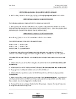
10-2: LMV51 Software Version Updates
This section covers all of the revisions that were made to the LMV51 controller with each new
software release. The software version of any LMV51 controller can be found using the
following menu path:
Params & Display > BurnerControl > SW Version
The LMV51.1 also has a load controller with its own unique software version. The software
version for the load controller can be found using the following menu path:
Params & Display > LoadController > SW Version
LMV51 Software Update: Version 0210 to 0220
The following updates were made with LMV51 software version 0220:
1.
When the unit reaches the
Program stop
position, the AZL5 displays “
Programstop active”.
2. Alarm output X3-02.1 can be deactivated via parameter
Alarm act/deact
. The current fault
or lockout is still maintained on the AZL, but the 120V output is de-energized. Deactivation of
the output remains active until a reset is made, another fault occurs, or a startup occurs.
3. A low oil pressure switch can now be activated when firing oil.
4. When firing oil, the oil safety valve output X6-03.3 de-energizes on completion of the
afterburn time (end of phase 70).
The fan output de-energizes after phase 79.
Using
parameter
OilPumpCoupling
, it is now possible to choose between the described above
(when
using the magnetic clutch) or direct coupling of the oil pump.
In the case of direct coupling, the
oil safety valve must be connected to the output for the oil pump (X6-02.3).
The oil safety is
will always be controlled when the fan runs, plus another 15
seconds.
5.
The evaluation of input
DWminOil
when using oil train “
Heavy oil with gas pilot”
has been
moved from phase 38 to phase 44.
DWminOil
is only valued during the safety time after a delay
time has elapsed.
6. The output signal to the air pressure switch test valve can be inverted using parameter
Start/PS-Valve
. This output is only active when the fan operates.
7. If the burner operation is set to “
Manually on”
, the burner on / off contact (X5-03.1) acts as
a shutoff device should an over-temperature situation occur.
With the exception of operating
mode 1 (ExtLC X5-03), the burner on / off contact can be
deactivated if not being used as a
shutoff device.
HOME
Содержание LMV 5 Series
Страница 2: ...Intentionally Left Blank ...
Страница 25: ...LMV Series Technical Instructions Document No LV5 1000 SCC Inc Page 21 Section 1 Intentionally Left Blank HOME ...
Страница 27: ...LMV Series Technical Instructions Document No LV5 1000 SCC Inc Page 23 Section 1 Intentionally Left Blank HOME ...
Страница 41: ...LMV Series Technical Instructions Document No LV5 1000 SCC Inc Page 7 Section 2 HOME ...
Страница 42: ...Technical Instructions LMV Series Document No LV5 1000 Section 2 Page 8 SCC Inc HOME ...
Страница 43: ...LMV Series Technical Instructions Document No LV5 1000 SCC Inc Page 9 Section 2 HOME ...
Страница 44: ...Technical Instructions LMV Series Document No LV5 1000 Section 2 Page 10 SCC Inc HOME ...
Страница 45: ...LMV Series Technical Instructions Document No LV5 1000 SCC Inc Page 11 Section 2 HOME ...
Страница 46: ...Technical Instructions LMV Series Document No LV5 1000 Section 2 Page 12 SCC Inc HOME ...
Страница 47: ...LMV Series Technical Instructions Document No LV5 1000 SCC Inc Page 13 Section 2 HOME ...
Страница 48: ...Technical Instructions LMV Series Document No LV5 1000 Section 2 Page 14 SCC Inc HOME ...
Страница 49: ...LMV Series Technical Instructions Document No LV5 1000 SCC Inc Page 15 Section 2 HOME ...
Страница 50: ...Technical Instructions LMV Series Document No LV5 1000 Section 2 Page 16 SCC Inc HOME ...
Страница 51: ...LMV Series Technical Instructions Document No LV5 1000 SCC Inc Page 17 Section 2 HOME ...
Страница 52: ...Technical Instructions LMV Series Document No LV5 1000 Section 2 Page 18 SCC Inc HOME ...
Страница 53: ...LMV Series Technical Instructions Document No LV5 1000 SCC Inc Page 19 Section 2 HOME ...
Страница 54: ...Technical Instructions LMV Series Document No LV5 1000 Section 2 Page 20 SCC Inc HOME ...
Страница 55: ...LMV Series Technical Instructions Document No LV5 1000 SCC Inc Page 21 Section 2 HOME ...
Страница 56: ...Technical Instructions LMV Series Document No LV5 1000 Section 2 Page 22 SCC Inc Intentionally Left Blank HOME ...
Страница 116: ...Technical Instructions LMV Series Document No LV5 1000 Section 3 Page 58 SCC Inc Intentionally Left Blank HOME ...
Страница 150: ...Technical Instructions LMV Series Document No LV5 1000 Section 4 Page 32 SCC Inc Intentionally Left Blank HOME ...
Страница 170: ...Technical Instructions LMV Series Document No LV5 1000 Section 5 Page 18 SCC Inc Intentionally Left Blank HOME ...
Страница 290: ...Technical Instructions LMV Series Document No LV5 1000 Section 8 Page 20 SCC Inc Intentionally Left Blank HOME ...
Страница 306: ...Technical Instructions LMV Series Document No LV5 1000 Section 9 Page 14 SCC Inc Intentionally Left Blank HOME ...
Страница 373: ...Intentionally Left Blank ...