

Technical
Instructions
LMV
Series
Document
No.
LV5
‐
1000
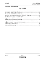
Section
4
Page
6
SCC
Inc.
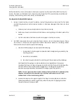
Configuring
(Parameterization
of)
an
LMV5
with
a
Default
Parameter
Set
The
procedure
below
assumes
an
LMV5
with
a
default
parameter
set.
If
the
LMV5
is
mounted
to
a
burner
/
boiler,
the
OEM(s)
may
have
already
changed
the
parameters
from
the
default
setting
and
parameterized
the
LMV5
for
the
application.
Section
3
(Parameters)
gives
a
detailed
explanation
of
all
of
the
parameters
in
the
LMV5,
as
well
as
highlights
which
parameters
must
be
set
(marked
with
a
double
asterisk
**)
and
which
parameters
are
frequently
used
(shaded).
This
procedure
gives
a
general
guideline
of
what
parameters
need
to
be
set
to
get
an
LMV5
running
on
a
typical
burner/
boiler.
Every
burner
is
different,
so
it
is
likely
that
every
burner
will
need
a
somewhat
unique
parameter
set
to
run
correctly.
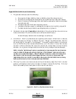
When
an
LMV5
with
a
default
parameter
set
is
powered
up
and
wired
correctly,
it
will
go
into
alarm
and
state
that
"no
fuel
train
is
defined".
During
the
parameterization,
the
alarm
does
not
need
to
be
reset.
Moreover,
the
alarm
will
come
back
immediately
until
at
least
a
few
key
parameters
are
set.
The
recommendation
is
to
silence
the
alarm
horn,
and
leave
the
LMV5
in
a
state
of
alarm
until
the
key
parameters
are
set.
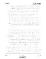
1.
Log
in
at
the
OEM
password
level.
From
the
factory,
the
OEM
password
for
the
LMV5
is
"START".
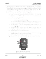
2.
Set
the
Burner
ID.
This
can
be
found
in
the
main
menu
under
Updating.
The
OEM
password
will
be
required
when
the
Updating
menu
is
entered.
The
Burner
ID
is
a
unique
number
which
matches
the
burner
to
the
parameter
set
in
the
LMV5.
Typically,
the
serial
number
of
the
burner
is
used
as
the
Burner
ID.
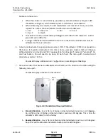
3.
Configure
the
load
controller
sensor
(except
LMV51.0…)
using
the
following
menu
path:
Params
&
Display
>
LoadController
>
Configuration
The
default
configuration
is
for
a
hot
water
boiler
(temperature
control)
with
a
PT100
RTD
temperature
sensor.
For
a
steam
boiler
(pressure
control),
set
the
following
parameters
to
the
following
settings:
Sensor
Select
=
PressSensor
Ext
Inp
X61
U/I
=
0..10V
or
4..20mA
(sensor
dependent)
MRangePressSens
=
High
range
of
pressure
sensor
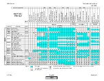
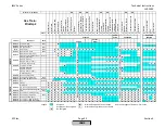
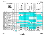
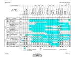
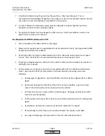
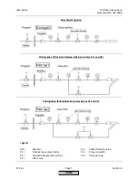
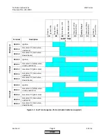
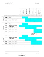
4.
Set
the
fuel
train(s).
If
only
gas
is
to
be
fired,
only
a
gas
fuel
train
must
be
selected.
If
only
oil
is
to
be
fired,
only
an
oil
fuel
train
must
be
selected.
For
dual
fuel
burners,
both
a
gas
and
oil
fuel
train
must
be
selected.
Fuel
trains
can
be
set
using
the
following
menu
path:
Params
&
Display
>
BurnerControl
>
Configuration
>
ConfigGeneral
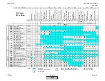
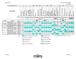
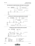
See
the
following
pages
for
fuel
train
information.
“Pilot
Gp2”
is
typical
for
gas
piloted
gas
burners
and
“LO
w
Gasp”
is
typical
for
gas
piloted
oil
burners.
HOME
Содержание LMV 5 Series
Страница 2: ...Intentionally Left Blank ...
Страница 25: ...LMV Series Technical Instructions Document No LV5 1000 SCC Inc Page 21 Section 1 Intentionally Left Blank HOME ...
Страница 27: ...LMV Series Technical Instructions Document No LV5 1000 SCC Inc Page 23 Section 1 Intentionally Left Blank HOME ...
Страница 41: ...LMV Series Technical Instructions Document No LV5 1000 SCC Inc Page 7 Section 2 HOME ...
Страница 42: ...Technical Instructions LMV Series Document No LV5 1000 Section 2 Page 8 SCC Inc HOME ...
Страница 43: ...LMV Series Technical Instructions Document No LV5 1000 SCC Inc Page 9 Section 2 HOME ...
Страница 44: ...Technical Instructions LMV Series Document No LV5 1000 Section 2 Page 10 SCC Inc HOME ...
Страница 45: ...LMV Series Technical Instructions Document No LV5 1000 SCC Inc Page 11 Section 2 HOME ...
Страница 46: ...Technical Instructions LMV Series Document No LV5 1000 Section 2 Page 12 SCC Inc HOME ...
Страница 47: ...LMV Series Technical Instructions Document No LV5 1000 SCC Inc Page 13 Section 2 HOME ...
Страница 48: ...Technical Instructions LMV Series Document No LV5 1000 Section 2 Page 14 SCC Inc HOME ...
Страница 49: ...LMV Series Technical Instructions Document No LV5 1000 SCC Inc Page 15 Section 2 HOME ...
Страница 50: ...Technical Instructions LMV Series Document No LV5 1000 Section 2 Page 16 SCC Inc HOME ...
Страница 51: ...LMV Series Technical Instructions Document No LV5 1000 SCC Inc Page 17 Section 2 HOME ...
Страница 52: ...Technical Instructions LMV Series Document No LV5 1000 Section 2 Page 18 SCC Inc HOME ...
Страница 53: ...LMV Series Technical Instructions Document No LV5 1000 SCC Inc Page 19 Section 2 HOME ...
Страница 54: ...Technical Instructions LMV Series Document No LV5 1000 Section 2 Page 20 SCC Inc HOME ...
Страница 55: ...LMV Series Technical Instructions Document No LV5 1000 SCC Inc Page 21 Section 2 HOME ...
Страница 56: ...Technical Instructions LMV Series Document No LV5 1000 Section 2 Page 22 SCC Inc Intentionally Left Blank HOME ...
Страница 116: ...Technical Instructions LMV Series Document No LV5 1000 Section 3 Page 58 SCC Inc Intentionally Left Blank HOME ...
Страница 150: ...Technical Instructions LMV Series Document No LV5 1000 Section 4 Page 32 SCC Inc Intentionally Left Blank HOME ...
Страница 170: ...Technical Instructions LMV Series Document No LV5 1000 Section 5 Page 18 SCC Inc Intentionally Left Blank HOME ...
Страница 290: ...Technical Instructions LMV Series Document No LV5 1000 Section 8 Page 20 SCC Inc Intentionally Left Blank HOME ...
Страница 306: ...Technical Instructions LMV Series Document No LV5 1000 Section 9 Page 14 SCC Inc Intentionally Left Blank HOME ...
Страница 373: ...Intentionally Left Blank ...