


LMV
Series
Technical
Instructions
Document
No.
LV5
‐
1000
SCC
Inc.
Page
3
Section
6
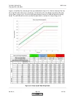
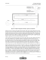
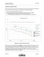
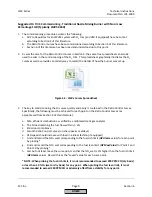
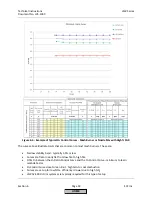
Figure
6
‐
1:
Physical
Arrangement
of
Burner,
O
2
Sensor,
and
Gas
Path
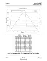
Since
the
O
2
sensor
is
located
in
the
boiler's
exhaust
(stack),
there
always
exists
a
delay
time
(Tau
time)
between
when
air
flow
is
adjusted
at
the
burner
and
when
the
change
is
detected
by
the
O
2
sensor.
This
physical
reality
forces
the
O
2
trim
to
use
"old"
O
2
readings,
which
will
be
discussed
later.
The
delay
time
depends
on
the
length
of
the
gas
path
through
the
boiler
and
the
velocity
of
the
gas.
The
length
of
the
gas
path
is
fixed
for
a
given
boiler,
but
the
gas
velocity
depends
upon
the
firing
rate.
Higher
firing
rates
equate
to
higher
gas
velocities
and
smaller
delay
times
(Tau
times).
If
the
fuel
flow
increases
linearly
with
the
firing
rate
(the
load
number
accurately
reflects
the
fuel
flow),
the
Tau
time
will
decrease
in
a
predictable
manner
as
the
firing
rate
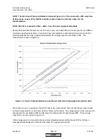
increases.
Likewise,
given
an
accurate
load
number,
the
Tau
time
will
increase
in
a
predictable
manner
as
the
firing
rate
decreases.
This
enables
the
Tau
time
to
be
automatically
calculated
at
every
point
from
Point
2
to
high
fire.
Once
the
Tau
time
is
calculated
for
every
point
from
Point
2
to
high
fire,
the
PI
(proportional
+
integral)
response
for
the
O
2
trim
can
be
automatically
calculated
for
every
point
between
Point
2
and
high
fire.
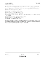
Another
place
where
the
Tau
time
must
be
accounted
for
is
at
startup.
Immediately
before
main
flame
ignition,
the
gas
path
of
the
boiler
is
full
of
air.
To
get
a
representative
O
2
reading
that
can
be
used
for
trimming,
the
gas
path
of
the
boiler
must
be
full
of
products
of
combustion
(exhaust
gases).
Thus,
the
main
flame
of
the
burner
must
be
ignited
and
the
burner
must
be
running
for
a
period
of
time
to
flush
out
all
of
the
air.
The
time
it
takes
to
flush
out
this
air
is
estimated
by
taking
the
Tau
time
(at
Point
2)
times
a
multiplier.
For
example,
if
the
Tau
time
at
Point
2
is
measured
to
be
6
seconds,
then
the
time
it
takes
to
get
a
representative
O
2
reading
after
light
off
might
be
6
x
6
=
36
seconds.
In
this
example,
closed
loop
O
2
trim
cannot
occur
until
36
seconds
after
light
off.
This
is
precisely
where
the
temperature
compensation
functionality
is
used
for
some
burners
(LMV52.440
only).
HOME
Содержание LMV 5 Series
Страница 2: ...Intentionally Left Blank ...
Страница 25: ...LMV Series Technical Instructions Document No LV5 1000 SCC Inc Page 21 Section 1 Intentionally Left Blank HOME ...
Страница 27: ...LMV Series Technical Instructions Document No LV5 1000 SCC Inc Page 23 Section 1 Intentionally Left Blank HOME ...
Страница 41: ...LMV Series Technical Instructions Document No LV5 1000 SCC Inc Page 7 Section 2 HOME ...
Страница 42: ...Technical Instructions LMV Series Document No LV5 1000 Section 2 Page 8 SCC Inc HOME ...
Страница 43: ...LMV Series Technical Instructions Document No LV5 1000 SCC Inc Page 9 Section 2 HOME ...
Страница 44: ...Technical Instructions LMV Series Document No LV5 1000 Section 2 Page 10 SCC Inc HOME ...
Страница 45: ...LMV Series Technical Instructions Document No LV5 1000 SCC Inc Page 11 Section 2 HOME ...
Страница 46: ...Technical Instructions LMV Series Document No LV5 1000 Section 2 Page 12 SCC Inc HOME ...
Страница 47: ...LMV Series Technical Instructions Document No LV5 1000 SCC Inc Page 13 Section 2 HOME ...
Страница 48: ...Technical Instructions LMV Series Document No LV5 1000 Section 2 Page 14 SCC Inc HOME ...
Страница 49: ...LMV Series Technical Instructions Document No LV5 1000 SCC Inc Page 15 Section 2 HOME ...
Страница 50: ...Technical Instructions LMV Series Document No LV5 1000 Section 2 Page 16 SCC Inc HOME ...
Страница 51: ...LMV Series Technical Instructions Document No LV5 1000 SCC Inc Page 17 Section 2 HOME ...
Страница 52: ...Technical Instructions LMV Series Document No LV5 1000 Section 2 Page 18 SCC Inc HOME ...
Страница 53: ...LMV Series Technical Instructions Document No LV5 1000 SCC Inc Page 19 Section 2 HOME ...
Страница 54: ...Technical Instructions LMV Series Document No LV5 1000 Section 2 Page 20 SCC Inc HOME ...
Страница 55: ...LMV Series Technical Instructions Document No LV5 1000 SCC Inc Page 21 Section 2 HOME ...
Страница 56: ...Technical Instructions LMV Series Document No LV5 1000 Section 2 Page 22 SCC Inc Intentionally Left Blank HOME ...
Страница 116: ...Technical Instructions LMV Series Document No LV5 1000 Section 3 Page 58 SCC Inc Intentionally Left Blank HOME ...
Страница 150: ...Technical Instructions LMV Series Document No LV5 1000 Section 4 Page 32 SCC Inc Intentionally Left Blank HOME ...
Страница 170: ...Technical Instructions LMV Series Document No LV5 1000 Section 5 Page 18 SCC Inc Intentionally Left Blank HOME ...
Страница 290: ...Technical Instructions LMV Series Document No LV5 1000 Section 8 Page 20 SCC Inc Intentionally Left Blank HOME ...
Страница 306: ...Technical Instructions LMV Series Document No LV5 1000 Section 9 Page 14 SCC Inc Intentionally Left Blank HOME ...
Страница 373: ...Intentionally Left Blank ...