

LMV Series
Technical Instructions
LV5-1000
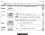
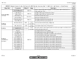
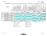
Menu Path
Parameter
Default
Range
Description
51.1
52.2
52.4
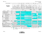
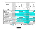
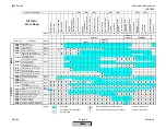
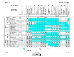
LEGEND -
Password Access:
(U)=User, (S)=Service, (O)=OEM, Shaded = Commonly Used, ** = Must Set, X = Has Function, / = Partial Function
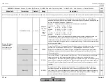
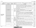
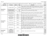
LMV
Params & Display>
O2 Module
SW Version (U)
Software version of the O2 module (PLL module).
x x
FGR-Mode (S)
Aux3on
Curve
Aux3onCurve
time
temperature
temp.contr.
TCautoDeact
deactMinpos
auto deact
Sets the mode of the FGR hold for the Aux 3 actuator. Seven seperate operating modes exist.
These are:
1) Aux3onCurve- Function deactivated and Aux 3 actuator always operates on its
programmed curve.
2) time - Aux 3 actuator stays at ignition position until
DelayTimeFGR Gas(Oil)
timer expires.
3) temperature - Aux 3 actuator stays at ignition position until
ThresholdFGR Gas(Oil)
temperature is reached.
4) temp.contr. - Position of Aux 3 actuator is based on flue temp,
Factor FGR Gas(Oil)
, and
the programmed curve for the Aux 3 actuator (LMV52.4 only).
5) TCautoDeact - same as Temp.contr but automatically deactivates if there is a fault with the
flue gas sensor (LMV52.4 only).
6) deactMinpos - after ignition position, Aux 3 actuator is held closed (LMV52.4 only).
7) auto deact - do not select this option. It is displayed if the FGR hold was deactivated due
to a sensor issue (LMV52.4 only).
/ x
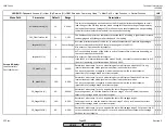
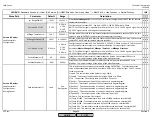
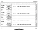
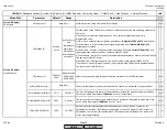
FGR-sensor (S)
X86PtNi
1000
X86PtNi1000
X60 Pt1000
X60 Ni1000
Selects the type and wiring location of the flue gas sensor for the FGR functions.
x x
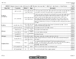
actTmpFGR-sensor (U)
The actual temperature read by the selected FGR sensor can be viewed at this parameter.
x x
ThresholdFGR Gas(Oil) (S)
752 F
32-1562 F
This sets the temperature that must be achieved to release the Aux 3 actuator to modulate.
Only has an effect if parameter
FGR-Mode
is set to "temperature".
x x
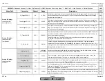
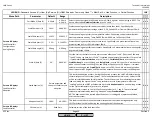
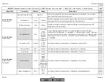
DelaytimeFGR Gas(Oil) (S)
300s
0-63min
This sets the time that must elapse before the Aux 3 actuator is released to modulate. Only
has an effect if parameter
FGR-Mode
is set to "time".
x x
Factor FGR Gas(Oil) (S)
100%
10-100%
Adjustment of calculated temperature dependent position of the Aux 3 actuator. An
adjustment of less than 100% reduces the position of the Aux 3 actuator. 100% means no
adjustment. Factor only has an effect when FGR temperature is different than when ratio
curves were commissioned.
x
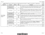
Read Only
Read Only
Params & Display>
Flue Gas Recirc.
SCC Inc.
Page 42
Section 3
HOME
HOME
P - LIST
Содержание LMV 5 Series
Страница 2: ...Intentionally Left Blank ...
Страница 25: ...LMV Series Technical Instructions Document No LV5 1000 SCC Inc Page 21 Section 1 Intentionally Left Blank HOME ...
Страница 27: ...LMV Series Technical Instructions Document No LV5 1000 SCC Inc Page 23 Section 1 Intentionally Left Blank HOME ...
Страница 41: ...LMV Series Technical Instructions Document No LV5 1000 SCC Inc Page 7 Section 2 HOME ...
Страница 42: ...Technical Instructions LMV Series Document No LV5 1000 Section 2 Page 8 SCC Inc HOME ...
Страница 43: ...LMV Series Technical Instructions Document No LV5 1000 SCC Inc Page 9 Section 2 HOME ...
Страница 44: ...Technical Instructions LMV Series Document No LV5 1000 Section 2 Page 10 SCC Inc HOME ...
Страница 45: ...LMV Series Technical Instructions Document No LV5 1000 SCC Inc Page 11 Section 2 HOME ...
Страница 46: ...Technical Instructions LMV Series Document No LV5 1000 Section 2 Page 12 SCC Inc HOME ...
Страница 47: ...LMV Series Technical Instructions Document No LV5 1000 SCC Inc Page 13 Section 2 HOME ...
Страница 48: ...Technical Instructions LMV Series Document No LV5 1000 Section 2 Page 14 SCC Inc HOME ...
Страница 49: ...LMV Series Technical Instructions Document No LV5 1000 SCC Inc Page 15 Section 2 HOME ...
Страница 50: ...Technical Instructions LMV Series Document No LV5 1000 Section 2 Page 16 SCC Inc HOME ...
Страница 51: ...LMV Series Technical Instructions Document No LV5 1000 SCC Inc Page 17 Section 2 HOME ...
Страница 52: ...Technical Instructions LMV Series Document No LV5 1000 Section 2 Page 18 SCC Inc HOME ...
Страница 53: ...LMV Series Technical Instructions Document No LV5 1000 SCC Inc Page 19 Section 2 HOME ...
Страница 54: ...Technical Instructions LMV Series Document No LV5 1000 Section 2 Page 20 SCC Inc HOME ...
Страница 55: ...LMV Series Technical Instructions Document No LV5 1000 SCC Inc Page 21 Section 2 HOME ...
Страница 56: ...Technical Instructions LMV Series Document No LV5 1000 Section 2 Page 22 SCC Inc Intentionally Left Blank HOME ...
Страница 116: ...Technical Instructions LMV Series Document No LV5 1000 Section 3 Page 58 SCC Inc Intentionally Left Blank HOME ...
Страница 150: ...Technical Instructions LMV Series Document No LV5 1000 Section 4 Page 32 SCC Inc Intentionally Left Blank HOME ...
Страница 170: ...Technical Instructions LMV Series Document No LV5 1000 Section 5 Page 18 SCC Inc Intentionally Left Blank HOME ...
Страница 290: ...Technical Instructions LMV Series Document No LV5 1000 Section 8 Page 20 SCC Inc Intentionally Left Blank HOME ...
Страница 306: ...Technical Instructions LMV Series Document No LV5 1000 Section 9 Page 14 SCC Inc Intentionally Left Blank HOME ...
Страница 373: ...Intentionally Left Blank ...