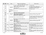
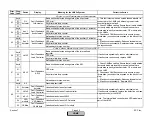
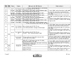
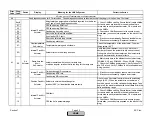

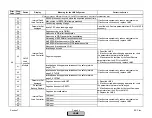
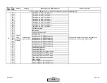
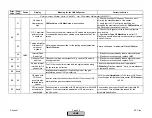
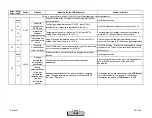

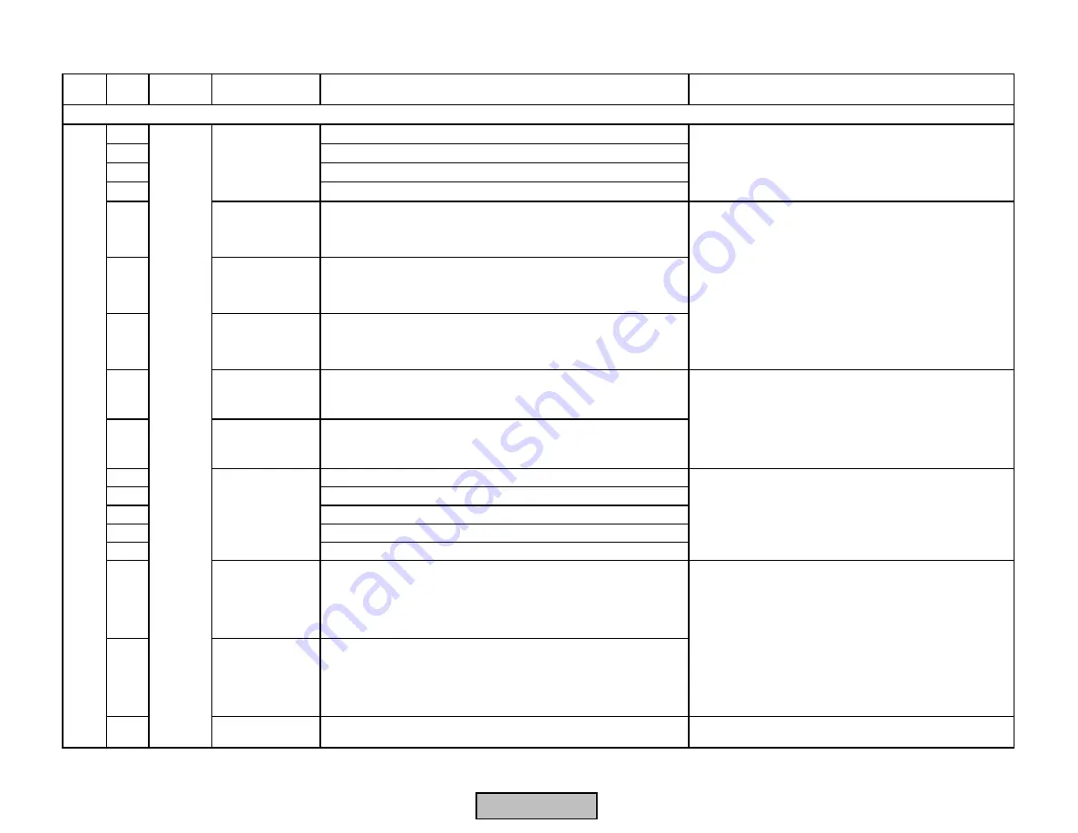
Error
Code
Diag.
Code
Device
Display
Meaning for the LMV5x System
Corrective Action
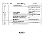
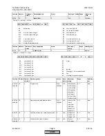
07
Sync fault or CRC fault
08
Error code for main loop counter
09
Fault during stack test
0A
Feedback values invalid
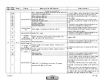
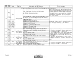
10
Unplaus Value
Nernst Voltage
O2 Module
Nernst voltage outside the valid range
12
Unplaus Value
Thermocouple O2
Module
Thermocouple voltage outside the valid range
13
Unplaus Value
Compensation
Element
Compensation element voltage outside the valid range
15
Unplaus Value
Flue Gas Temp
O2 Module
Temperature of combustion air sensor outside the valid range
(-20...+800 °C)
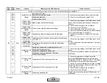
16
Unplaus Value
Flue Gas Temp
O2 Module
Temperature of flue gas sensor outside the valid range (-
20...+800 °C)
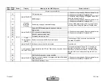
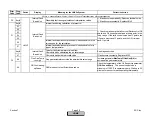
17
Fault during combustion air temperature sensor test
18
Fault during thermocouple test
19
Fault during compensation element test
1A
Fault during channel comparison of O2 signal
1B
Fault ADC test voltages
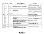
20
O2 Sensor Temp
too low
Temperature of QGO measuring cell too low
21
O2 Sensor Temp
too high
Temperature of QGO measuring cell too high
22
Internal Fault O2
Module
Fault during calculation test
If fault occurs constantly, replace O2 Sensor and / or
O2 Module
1) If fault occurs sporadically, reduce electrical noise.
2) If fault occurs continuously, replace PLL5..
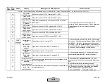
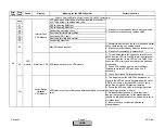
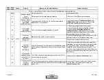
Internal Fault O2
Module
1) Check the wiring between the O2 Module and the O2
sensor. Ensure high and low voltage are in seperate
conduits.
2) Check the power supply to the O2 Module
3) Check fuse in the O2 Module
4) Check the heating control on the O2 Sensor
5) Check the temperature inside the O2 Sensor terminal
box. Should be between -13 and 248
o
F
5) If fault occurs constantly, Replace O2 Sensor and /
or Module.
Fault with 02 Module (PLL5..) or Oxygen Sensor (QGO2..)
1) Check the wiring between the O2 Module and the O2
sensor.
2) Check the ambient / flue gas temperature. Compare
to valid range.
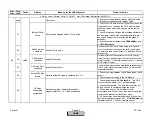
1) Check the wiring between the O2 Module and the O2
sensor.
2) If fault occurs constantly, replace O2 Sensor and / or
O2 Module
Internal Fault O2
Module
1) Check the temperature of heated sensor via
parameter
QGO SensorTemp.
Minimum operating
termperature is 1202
°
F, maximum 1382
°
F. O2 sensor
could take up to 20 minutes to reach temperature.
2) Ensure O2 sensor is installed properly (see mounting
section) and that stack gas velocity is correct. Min = 3.2
ft / sec, max = 32 ft / sec.
3) Check the power supply to the O2 Module
4) Check fuse in the O2 Module
PLL5..
AB
Section 7
Page 53
SCC Inc.
HOME
HOME
Содержание LMV 5 Series
Страница 2: ...Intentionally Left Blank ...
Страница 25: ...LMV Series Technical Instructions Document No LV5 1000 SCC Inc Page 21 Section 1 Intentionally Left Blank HOME ...
Страница 27: ...LMV Series Technical Instructions Document No LV5 1000 SCC Inc Page 23 Section 1 Intentionally Left Blank HOME ...
Страница 41: ...LMV Series Technical Instructions Document No LV5 1000 SCC Inc Page 7 Section 2 HOME ...
Страница 42: ...Technical Instructions LMV Series Document No LV5 1000 Section 2 Page 8 SCC Inc HOME ...
Страница 43: ...LMV Series Technical Instructions Document No LV5 1000 SCC Inc Page 9 Section 2 HOME ...
Страница 44: ...Technical Instructions LMV Series Document No LV5 1000 Section 2 Page 10 SCC Inc HOME ...
Страница 45: ...LMV Series Technical Instructions Document No LV5 1000 SCC Inc Page 11 Section 2 HOME ...
Страница 46: ...Technical Instructions LMV Series Document No LV5 1000 Section 2 Page 12 SCC Inc HOME ...
Страница 47: ...LMV Series Technical Instructions Document No LV5 1000 SCC Inc Page 13 Section 2 HOME ...
Страница 48: ...Technical Instructions LMV Series Document No LV5 1000 Section 2 Page 14 SCC Inc HOME ...
Страница 49: ...LMV Series Technical Instructions Document No LV5 1000 SCC Inc Page 15 Section 2 HOME ...
Страница 50: ...Technical Instructions LMV Series Document No LV5 1000 Section 2 Page 16 SCC Inc HOME ...
Страница 51: ...LMV Series Technical Instructions Document No LV5 1000 SCC Inc Page 17 Section 2 HOME ...
Страница 52: ...Technical Instructions LMV Series Document No LV5 1000 Section 2 Page 18 SCC Inc HOME ...
Страница 53: ...LMV Series Technical Instructions Document No LV5 1000 SCC Inc Page 19 Section 2 HOME ...
Страница 54: ...Technical Instructions LMV Series Document No LV5 1000 Section 2 Page 20 SCC Inc HOME ...
Страница 55: ...LMV Series Technical Instructions Document No LV5 1000 SCC Inc Page 21 Section 2 HOME ...
Страница 56: ...Technical Instructions LMV Series Document No LV5 1000 Section 2 Page 22 SCC Inc Intentionally Left Blank HOME ...
Страница 116: ...Technical Instructions LMV Series Document No LV5 1000 Section 3 Page 58 SCC Inc Intentionally Left Blank HOME ...
Страница 150: ...Technical Instructions LMV Series Document No LV5 1000 Section 4 Page 32 SCC Inc Intentionally Left Blank HOME ...
Страница 170: ...Technical Instructions LMV Series Document No LV5 1000 Section 5 Page 18 SCC Inc Intentionally Left Blank HOME ...
Страница 290: ...Technical Instructions LMV Series Document No LV5 1000 Section 8 Page 20 SCC Inc Intentionally Left Blank HOME ...
Страница 306: ...Technical Instructions LMV Series Document No LV5 1000 Section 9 Page 14 SCC Inc Intentionally Left Blank HOME ...
Страница 373: ...Intentionally Left Blank ...