

LMV
Series
Technical
Instructions
LV5
‐
1000
SCC
Inc.
Page
47
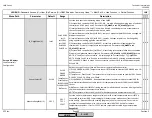
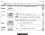
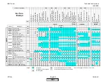
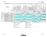
Section
3
3
‐
3:
Sequence
Diagrams
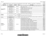
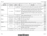
The
Siemens
LMV5
BMS
can
perform
a
number
of
different
burner
sequences
based
upon
how
certain
parameters
are
set.
Although
there
are
a
number
of
parameters
that
affect
small
aspects
of
the
burner
sequence,
the
main
parameters
that
affect
the
sequence
are
parameters
FuelTrainGas
and
FuelTrainOil
.
These
parameters
set
the
framework
of
the
sequence
and
are
based
upon
the
fuel
train
diagrams
in
Section
4.
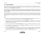
The
OEM
has
the
option
of
selecting
one
of
three
different
gas
trains
with
their
associated
sequence
diagrams,
and
one
of
four
different
oil
trains
with
their
associated
sequence
diagrams
(the
sequence
diagrams
and
fuel
train
diagrams
for
direct
spark
ignition
with
heavy
oil
have
been
omitted).
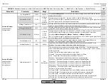
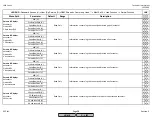
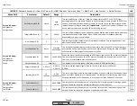
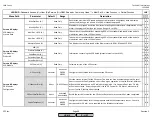
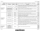
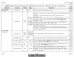
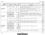
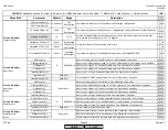
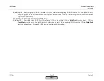
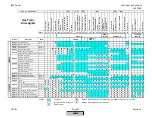
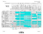
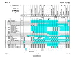
The
sequence
diagrams
in
Section
3
‐
3
illustrate
when
input
and
output
terminals
are
expected
to
be
energized
or
de
‐
energized.
A
legend
on
the
bottom
of
each
page
describes
the
various
symbols
used
in
the
diagrams.
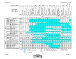
The
last
diagram
describes
what
positions
the
attached
actuators
are
expected
to
achieve
at
each
phase
and
outlines
the
method
that
is
used
to
check
the
actuators
position.
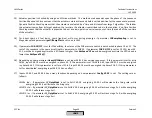
Notes
:
1)
Only
one
fuel
select
terminal
can
be
energized
at
a
time.
If
both
terminals
are
energized,
the
LMV5
will
go
into
lockout.
If
neither
terminal
is
energized,
fuel
selection
is
internal
through
the
AZL5
(
FuelSelect
)
or
via
Modbus.
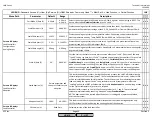
2)
The
external
burner
on
/
off
switch
can
be
disabled
with
parameter
InputController
.
If
activated,
this
terminal
needs
to
be
energized
to
have
the
LMV5
start
its
sequence.
The
function
of
terminal
X5
‐
03.1
becomes
“burner
on
/
off”
when
any
external
load
control
mode
is
selected.
3)
The
alarm
can
be
silenced
through
the
AZL
(
Alarm
act/deact
).
This
alarm
silence
resets
when
the
LMV5
is
reset
or
restarted.
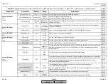
4)
When
using
an
LMV52,
continuous
pilot
is
possible
(
ContPilotGas
/
ContPilotOil
).
If
continuous
pilot
is
activated,
the
pilot
valve
will
remain
energized
through
phase
62.
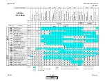
5)
If
parameter
GasPressureMin
is
set
to
activated
,
the
low
gas
pressure
switch
is
expected
to
remain
closed
during
phases
21
‐
50
of
LO
w
Gasp
and
HO
w
Gasp
,
ensuring
adequate
gas
pressure
for
the
pilot.
If
GasPressureMin
is
set
to
Deact
xOGP
,
the
low
gas
pressure
switch
is
expected
to
remain
closed
only
when
firing
gas
and
is
not
checked
when
firing
oil.
HOMEHOME
HOME
Содержание LMV 5 Series
Страница 2: ...Intentionally Left Blank ...
Страница 25: ...LMV Series Technical Instructions Document No LV5 1000 SCC Inc Page 21 Section 1 Intentionally Left Blank HOME ...
Страница 27: ...LMV Series Technical Instructions Document No LV5 1000 SCC Inc Page 23 Section 1 Intentionally Left Blank HOME ...
Страница 41: ...LMV Series Technical Instructions Document No LV5 1000 SCC Inc Page 7 Section 2 HOME ...
Страница 42: ...Technical Instructions LMV Series Document No LV5 1000 Section 2 Page 8 SCC Inc HOME ...
Страница 43: ...LMV Series Technical Instructions Document No LV5 1000 SCC Inc Page 9 Section 2 HOME ...
Страница 44: ...Technical Instructions LMV Series Document No LV5 1000 Section 2 Page 10 SCC Inc HOME ...
Страница 45: ...LMV Series Technical Instructions Document No LV5 1000 SCC Inc Page 11 Section 2 HOME ...
Страница 46: ...Technical Instructions LMV Series Document No LV5 1000 Section 2 Page 12 SCC Inc HOME ...
Страница 47: ...LMV Series Technical Instructions Document No LV5 1000 SCC Inc Page 13 Section 2 HOME ...
Страница 48: ...Technical Instructions LMV Series Document No LV5 1000 Section 2 Page 14 SCC Inc HOME ...
Страница 49: ...LMV Series Technical Instructions Document No LV5 1000 SCC Inc Page 15 Section 2 HOME ...
Страница 50: ...Technical Instructions LMV Series Document No LV5 1000 Section 2 Page 16 SCC Inc HOME ...
Страница 51: ...LMV Series Technical Instructions Document No LV5 1000 SCC Inc Page 17 Section 2 HOME ...
Страница 52: ...Technical Instructions LMV Series Document No LV5 1000 Section 2 Page 18 SCC Inc HOME ...
Страница 53: ...LMV Series Technical Instructions Document No LV5 1000 SCC Inc Page 19 Section 2 HOME ...
Страница 54: ...Technical Instructions LMV Series Document No LV5 1000 Section 2 Page 20 SCC Inc HOME ...
Страница 55: ...LMV Series Technical Instructions Document No LV5 1000 SCC Inc Page 21 Section 2 HOME ...
Страница 56: ...Technical Instructions LMV Series Document No LV5 1000 Section 2 Page 22 SCC Inc Intentionally Left Blank HOME ...
Страница 116: ...Technical Instructions LMV Series Document No LV5 1000 Section 3 Page 58 SCC Inc Intentionally Left Blank HOME ...
Страница 150: ...Technical Instructions LMV Series Document No LV5 1000 Section 4 Page 32 SCC Inc Intentionally Left Blank HOME ...
Страница 170: ...Technical Instructions LMV Series Document No LV5 1000 Section 5 Page 18 SCC Inc Intentionally Left Blank HOME ...
Страница 290: ...Technical Instructions LMV Series Document No LV5 1000 Section 8 Page 20 SCC Inc Intentionally Left Blank HOME ...
Страница 306: ...Technical Instructions LMV Series Document No LV5 1000 Section 9 Page 14 SCC Inc Intentionally Left Blank HOME ...
Страница 373: ...Intentionally Left Blank ...