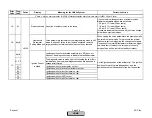
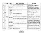
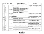

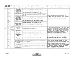
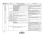
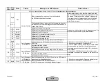

Error
Code
Diag.
Code
Device
Display
Meaning for the LMV5x System
Corrective Action
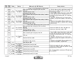
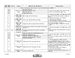
A0
Any #
Air actuator has detected own fault and reported it to the basic
unit. Type of fault: See diagnostic code
01
CRC fault during ROM test
02
CRC fault during RAM test
04
Fault during key value check
05
Error code for time block overflow
07
Sync fault or CRC fault
08
Error code for main loop counter
09
Fault during stack test
0C
Overtemperature
Air Actuator
Temperature warning and shutdown
Check the temperature of the air actuator. The max.
temperature 140
°
F.
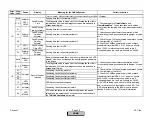
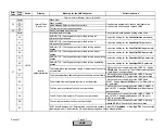
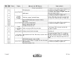
0D
Internal Fault Air
Actuator
Actuator turns in the wrong direction
Verify that the air damper is not stuck. A stuck air
damper will cause the actuator to trip on overcurrent.
During this short trip the actuator can be momentarily
pushed backwards by torsional effects.
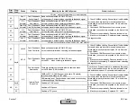
0E
Ramp time too
short
Air Actuator
Actuator operates with too short a ramp time,
or with an angular rotation that is too long for the ramp time
1) Match ramp time to the slowest connected actuator
(SQM48.4 - 30 sec, SQM48.6 - 60sec, SQM9 - 30 sec)
2) Check the CANBus power supply. Verify fuses FU2
and FU3 are ok. Verify CANBus is not overloaded (see
wiring section).
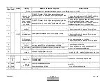
10
Timeout during A/D conversion
11
Fault during ADC test
12
Fault during A/D conversion
13
Position Fault Air
Actuator
Actuator is outside the valid angular
rotation (0-90°) or linearization data are faulty
Check to see if actuator is within the valid positioning
range (0-90°). When the actuator is not powered, it
could be moved out of the valid positioning range. Take
power off the actuator and position shaft back within the
valid positioning range.
15
CAN fault
16
CRC fault of a parameter page
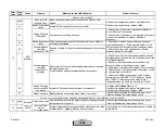
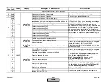
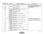
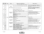
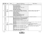
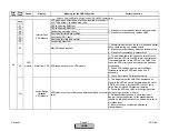
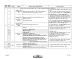
Fault with Connected Actuators
Air
Actuator
Internal Fault Air
Actuator
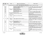
A1
1) Check CANBus cabling. Ensure that all cable shields
(screens) which are located in the cable sheath are
terminated correctly at each actuator, O2 module, and
at the LMV5x...
2) Check each CANBus connector to ensure proper
termination (no conductors exposed on the back of the
plug)
3) If fault occurs sporadically: Reduce electrical noise.
4) If fault occurs constantly: Replace air actuator
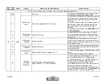
See diagnostic codes for A1 error codes. These diagnostic codes are identical, except they apply to the Auxiliary 3 Actuator.
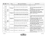
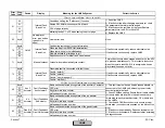
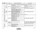
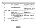
1) Check CANBus cabling. Ensure that all cable shields
(screens) which are located in the cable sheath are
terminated correctly at each actuator, O2 module, and
at the LMV5x...
2) Check each CANBus connector to ensure proper
termination (no conductors exposed on the back of the
plug)
1) If fault occurs sporadically, reduce electrical noise.
2) If fault occurs constantly, replace air actuator.
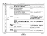
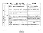
Internal Fault Air
Actuator
Internal Fault Air
Actuator
Section 7
Page 42
SCC Inc.
HOME
HOME
Содержание LMV 5 Series
Страница 2: ...Intentionally Left Blank ...
Страница 25: ...LMV Series Technical Instructions Document No LV5 1000 SCC Inc Page 21 Section 1 Intentionally Left Blank HOME ...
Страница 27: ...LMV Series Technical Instructions Document No LV5 1000 SCC Inc Page 23 Section 1 Intentionally Left Blank HOME ...
Страница 41: ...LMV Series Technical Instructions Document No LV5 1000 SCC Inc Page 7 Section 2 HOME ...
Страница 42: ...Technical Instructions LMV Series Document No LV5 1000 Section 2 Page 8 SCC Inc HOME ...
Страница 43: ...LMV Series Technical Instructions Document No LV5 1000 SCC Inc Page 9 Section 2 HOME ...
Страница 44: ...Technical Instructions LMV Series Document No LV5 1000 Section 2 Page 10 SCC Inc HOME ...
Страница 45: ...LMV Series Technical Instructions Document No LV5 1000 SCC Inc Page 11 Section 2 HOME ...
Страница 46: ...Technical Instructions LMV Series Document No LV5 1000 Section 2 Page 12 SCC Inc HOME ...
Страница 47: ...LMV Series Technical Instructions Document No LV5 1000 SCC Inc Page 13 Section 2 HOME ...
Страница 48: ...Technical Instructions LMV Series Document No LV5 1000 Section 2 Page 14 SCC Inc HOME ...
Страница 49: ...LMV Series Technical Instructions Document No LV5 1000 SCC Inc Page 15 Section 2 HOME ...
Страница 50: ...Technical Instructions LMV Series Document No LV5 1000 Section 2 Page 16 SCC Inc HOME ...
Страница 51: ...LMV Series Technical Instructions Document No LV5 1000 SCC Inc Page 17 Section 2 HOME ...
Страница 52: ...Technical Instructions LMV Series Document No LV5 1000 Section 2 Page 18 SCC Inc HOME ...
Страница 53: ...LMV Series Technical Instructions Document No LV5 1000 SCC Inc Page 19 Section 2 HOME ...
Страница 54: ...Technical Instructions LMV Series Document No LV5 1000 Section 2 Page 20 SCC Inc HOME ...
Страница 55: ...LMV Series Technical Instructions Document No LV5 1000 SCC Inc Page 21 Section 2 HOME ...
Страница 56: ...Technical Instructions LMV Series Document No LV5 1000 Section 2 Page 22 SCC Inc Intentionally Left Blank HOME ...
Страница 116: ...Technical Instructions LMV Series Document No LV5 1000 Section 3 Page 58 SCC Inc Intentionally Left Blank HOME ...
Страница 150: ...Technical Instructions LMV Series Document No LV5 1000 Section 4 Page 32 SCC Inc Intentionally Left Blank HOME ...
Страница 170: ...Technical Instructions LMV Series Document No LV5 1000 Section 5 Page 18 SCC Inc Intentionally Left Blank HOME ...
Страница 290: ...Technical Instructions LMV Series Document No LV5 1000 Section 8 Page 20 SCC Inc Intentionally Left Blank HOME ...
Страница 306: ...Technical Instructions LMV Series Document No LV5 1000 Section 9 Page 14 SCC Inc Intentionally Left Blank HOME ...
Страница 373: ...Intentionally Left Blank ...