


Technical Instructions
LMV Series
Document No. LV5-8000
Appendix A
Page 30
SCC Inc.
Remote Setpoint
Introduction
The LMV5 can be configured to accept either a local setpoint or a remote setpoint. A remote
setpoint takes an analog input and converts it into a setpoint. On the LMV5, terminal X62 can
be wired and configured to accept a variety of signals for a remote setpoint. The following
steps describe the procedure for setting up a remote setpoint on the LMV5.
Procedure
1.
Log in to the LMV5 with either the service or OEM level password.
2.
The LMV5 must be set for a load controller operating mode of “IntLC X62”. The LMV5
will utilize the internal PID loop, but will also respond to a remote setpoint from an
analog signal on terminal X62. To set the load controller operating mode to “IntLC X62”,
use the following menu path:
Params & Display > LoadController > Configuration > LC_OptgMode =
IntLC X62
3.
Configure the type of analog signal which will be input to terminal X62. Four options are
available: 0-10 Vdc, 2-10 Vdc, 0-20 mA, or 4-20 mA. Use the following menu path to set
the input type for terminal X62:
Params & Display > LoadController > Configuration > Ext Inp X62 U/I
NOTE: For the remainder of this section, all examples will use a 4-20 mA signal.
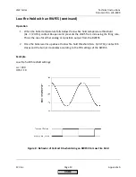
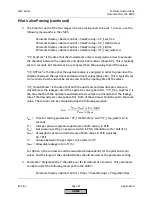
4.
The analog input must be scaled appropriately depending on the desired setpoint limits
for the remote setpoint. The LMV5 predefines what setpoint a 4 mA signal indicates.
Conversely, the LMV5 must be programmed with the desired setpoint for a 20 mA
signal. Then, the setpoint will be scaled linearly for any signal between 4 and 20 mA.
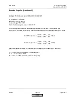
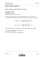
Low Setpoint Scaling
When operating on pressure, a 4 mA signal
always
translates to a 0 psi setpoint.
When operating on temperature, a 4 mA signal
always
translates to a 32°F setpoint.
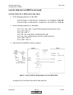
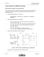
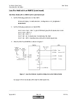
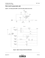
High Setpoint Scaling
The high end of the setpoint scaling depends on the sensor type wired to terminals X60
or X61. There are three possibilities for sensor type: a pressure sensor wired to
terminal X61, a temperature sensor wired to terminal X60, or a temperature transmitter
wired to terminal X61.
HOME
Содержание LMV 5 Series
Страница 2: ...Intentionally Left Blank ...
Страница 25: ...LMV Series Technical Instructions Document No LV5 1000 SCC Inc Page 21 Section 1 Intentionally Left Blank HOME ...
Страница 27: ...LMV Series Technical Instructions Document No LV5 1000 SCC Inc Page 23 Section 1 Intentionally Left Blank HOME ...
Страница 41: ...LMV Series Technical Instructions Document No LV5 1000 SCC Inc Page 7 Section 2 HOME ...
Страница 42: ...Technical Instructions LMV Series Document No LV5 1000 Section 2 Page 8 SCC Inc HOME ...
Страница 43: ...LMV Series Technical Instructions Document No LV5 1000 SCC Inc Page 9 Section 2 HOME ...
Страница 44: ...Technical Instructions LMV Series Document No LV5 1000 Section 2 Page 10 SCC Inc HOME ...
Страница 45: ...LMV Series Technical Instructions Document No LV5 1000 SCC Inc Page 11 Section 2 HOME ...
Страница 46: ...Technical Instructions LMV Series Document No LV5 1000 Section 2 Page 12 SCC Inc HOME ...
Страница 47: ...LMV Series Technical Instructions Document No LV5 1000 SCC Inc Page 13 Section 2 HOME ...
Страница 48: ...Technical Instructions LMV Series Document No LV5 1000 Section 2 Page 14 SCC Inc HOME ...
Страница 49: ...LMV Series Technical Instructions Document No LV5 1000 SCC Inc Page 15 Section 2 HOME ...
Страница 50: ...Technical Instructions LMV Series Document No LV5 1000 Section 2 Page 16 SCC Inc HOME ...
Страница 51: ...LMV Series Technical Instructions Document No LV5 1000 SCC Inc Page 17 Section 2 HOME ...
Страница 52: ...Technical Instructions LMV Series Document No LV5 1000 Section 2 Page 18 SCC Inc HOME ...
Страница 53: ...LMV Series Technical Instructions Document No LV5 1000 SCC Inc Page 19 Section 2 HOME ...
Страница 54: ...Technical Instructions LMV Series Document No LV5 1000 Section 2 Page 20 SCC Inc HOME ...
Страница 55: ...LMV Series Technical Instructions Document No LV5 1000 SCC Inc Page 21 Section 2 HOME ...
Страница 56: ...Technical Instructions LMV Series Document No LV5 1000 Section 2 Page 22 SCC Inc Intentionally Left Blank HOME ...
Страница 116: ...Technical Instructions LMV Series Document No LV5 1000 Section 3 Page 58 SCC Inc Intentionally Left Blank HOME ...
Страница 150: ...Technical Instructions LMV Series Document No LV5 1000 Section 4 Page 32 SCC Inc Intentionally Left Blank HOME ...
Страница 170: ...Technical Instructions LMV Series Document No LV5 1000 Section 5 Page 18 SCC Inc Intentionally Left Blank HOME ...
Страница 290: ...Technical Instructions LMV Series Document No LV5 1000 Section 8 Page 20 SCC Inc Intentionally Left Blank HOME ...
Страница 306: ...Technical Instructions LMV Series Document No LV5 1000 Section 9 Page 14 SCC Inc Intentionally Left Blank HOME ...
Страница 373: ...Intentionally Left Blank ...