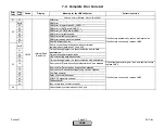
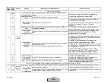
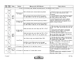
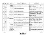
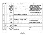
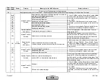

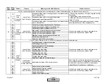

Error
Code
Diag.
Code
Device
Display
Meaning for the LMV5x System
Corrective Action
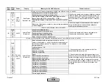
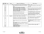
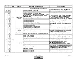
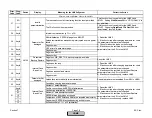
29
Any #
Fan Contactor
Contact is on
FCC signal = on, but should have been off
Any #
00
01
The error message may be traced back to an open
safety loop / burner flange.
2B
Any #
Flue Gas
Recirculation
Pressure Switch
on
FGR-PS = on, but should have been off
Any #
00
01
The error message may be traced back to an open
safety loop / burner flange.
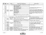
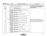
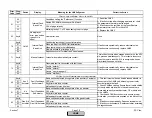
Any #
00
01
CPI via terminal StartRelease_Gas Closed Position Indicator
(CPI) = on, but should have been off
Any #
00
01
CPI via terminal StartRelease_Gas Closed Position Indicator
(CPI) = off, but should have been on
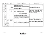
2F
Any #
Gas Pressure has
dropped below
minimum Limit
Low gas pressure switch is open
1) Check gas supply and / or manual shutoff valves.
2) Check setpoint and / or wiring of low gas pressure
switch.
30
Any #
Gas Pressure has
exceeded
maximum Limit
High gas pressure switch is open
1) Check pressure regulators for ruptured diaphragms.
2) Check setpoint and / or wiring of high gas pressure
switch.
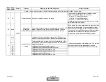
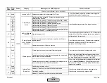
Fault with devices or wiring connected to the Base Unit (LMV5)
FCC signal = off, but should have been on
1) Check setpoint on FGR pressure switch. Adjust if
necessary.
2) If a FGR-PS fault occurs in Phase 70, call a siemens
representitve. A spark killer may be necessary.
Valve not open
Closed Position Indicator (CPI) = off, but should have been on
1) Check wiring to the fuel valves. Ensure fuel valves
are wired to the correct terminal (see wiring diagram).
With manual shutoff valves closed, ensure that the fuel
valves are opening in the proper phase (see sequence
diagrams).
2) Check wiring of the CPI (POC) switches. See wiring
diagram.
1) Check wiring to the fuel valves. With manual shutoff
valves closed, ensure that the fuel valves are opening
in the proper phase (see sequence diagrams).
2) Ensure CPI (POC) switches are opening when the
valve opens. If this does not happen, check wiring,
adjust switch, or replace fuel valve actuator.
2D
2E
Closed Position Indicator (CPI) = on, but should have been off
Valve or Closed
Position Indicator
(CPI) open
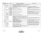
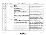
2A
Fan Contactor
Contact is off
1) If not using FCC, make sure parameter
FGR-
PS/FCC
is not set to "FCC".
2) If an FCC fault occurs in phase 70, call a Siemens
representative. A spark killer may be necessary.
Devices
conn. to
LMV5
2C
Flue Gas
Recirculation
Pressure Switch
off
FGR-PS = off, but should have been on
Section 7
Page 32
SCC Inc.
HOME
HOME
Содержание LMV 5 Series
Страница 2: ...Intentionally Left Blank ...
Страница 25: ...LMV Series Technical Instructions Document No LV5 1000 SCC Inc Page 21 Section 1 Intentionally Left Blank HOME ...
Страница 27: ...LMV Series Technical Instructions Document No LV5 1000 SCC Inc Page 23 Section 1 Intentionally Left Blank HOME ...
Страница 41: ...LMV Series Technical Instructions Document No LV5 1000 SCC Inc Page 7 Section 2 HOME ...
Страница 42: ...Technical Instructions LMV Series Document No LV5 1000 Section 2 Page 8 SCC Inc HOME ...
Страница 43: ...LMV Series Technical Instructions Document No LV5 1000 SCC Inc Page 9 Section 2 HOME ...
Страница 44: ...Technical Instructions LMV Series Document No LV5 1000 Section 2 Page 10 SCC Inc HOME ...
Страница 45: ...LMV Series Technical Instructions Document No LV5 1000 SCC Inc Page 11 Section 2 HOME ...
Страница 46: ...Technical Instructions LMV Series Document No LV5 1000 Section 2 Page 12 SCC Inc HOME ...
Страница 47: ...LMV Series Technical Instructions Document No LV5 1000 SCC Inc Page 13 Section 2 HOME ...
Страница 48: ...Technical Instructions LMV Series Document No LV5 1000 Section 2 Page 14 SCC Inc HOME ...
Страница 49: ...LMV Series Technical Instructions Document No LV5 1000 SCC Inc Page 15 Section 2 HOME ...
Страница 50: ...Technical Instructions LMV Series Document No LV5 1000 Section 2 Page 16 SCC Inc HOME ...
Страница 51: ...LMV Series Technical Instructions Document No LV5 1000 SCC Inc Page 17 Section 2 HOME ...
Страница 52: ...Technical Instructions LMV Series Document No LV5 1000 Section 2 Page 18 SCC Inc HOME ...
Страница 53: ...LMV Series Technical Instructions Document No LV5 1000 SCC Inc Page 19 Section 2 HOME ...
Страница 54: ...Technical Instructions LMV Series Document No LV5 1000 Section 2 Page 20 SCC Inc HOME ...
Страница 55: ...LMV Series Technical Instructions Document No LV5 1000 SCC Inc Page 21 Section 2 HOME ...
Страница 56: ...Technical Instructions LMV Series Document No LV5 1000 Section 2 Page 22 SCC Inc Intentionally Left Blank HOME ...
Страница 116: ...Technical Instructions LMV Series Document No LV5 1000 Section 3 Page 58 SCC Inc Intentionally Left Blank HOME ...
Страница 150: ...Technical Instructions LMV Series Document No LV5 1000 Section 4 Page 32 SCC Inc Intentionally Left Blank HOME ...
Страница 170: ...Technical Instructions LMV Series Document No LV5 1000 Section 5 Page 18 SCC Inc Intentionally Left Blank HOME ...
Страница 290: ...Technical Instructions LMV Series Document No LV5 1000 Section 8 Page 20 SCC Inc Intentionally Left Blank HOME ...
Страница 306: ...Technical Instructions LMV Series Document No LV5 1000 Section 9 Page 14 SCC Inc Intentionally Left Blank HOME ...
Страница 373: ...Intentionally Left Blank ...