


Technical
Instructions
LMV
Series
Document
No.
LV5
‐
1000
Section
6
Page
10
SCC
Inc.
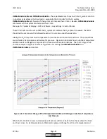
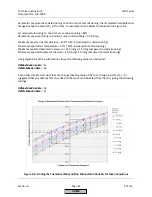
NOTE:
The
%O
2
values
read
and
displayed
by
the
LMV52
system
are
always
on
a
wet
basis
(%O
2
wet).
Most
if
not
all
external
exhaust
gas
analyzers
read
and
display
%O
2
and
other
gases
on
a
dry
basis
(%O
2
dry).
All
O
2
curves
must
be
commissioned
using
%O
2
wet
values
as
read
by
the
LMV52.
The
external
exhaust
gas
analyzer
is
used
to
read
CO,
NOx,
and
also
serves
as
a
way
to
double
check
the
%O
2
wet
values.
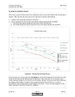
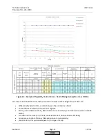
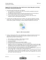
Figure
6
‐
11
gives
the
approximate
relationship
between
%O
2
wet
and
%O
2
dry.
4.
Make
sure
that
the
QGO20
O
2
sensor
has
been
activated
for
at
least
2
hours
and
is
up
to
temperature.
This
gives
the
Zirconium
cell
time
to
heat
‐
soak
and
also
to
burn
off
any
contaminants.
The
temperature
of
the
cell
can
be
checked
if
desired
through
the
following
menu
path:
Params
&
Display
>
O2
Module
>
Process
Data
>
QGO
SensorTemp
5.
With
the
burner
off
(Phase
12),
set
the
fuel
rich
limit
(
O2
Alarm
value)
for
each
point.
This
can
be
done
with
the
burner
off
since
these
values
have
already
been
found
and
recorded
during
Ratio
Control
Curve
commissioning
(see
above).
Once
into
the
O2
Alarm
curve,
simply
enter
in
the
recorded
value
for
each
point
and
save
each
point.
To
access
the
O2
Alarm
curve,
use
the
following
menu
path:
Params
&
Display
>
O2
Contr/Alarm
>
Gas
Settings
>
O2
Alarm
>
O2
Alarm
6.
With
the
burner
off
(Phase
12),
set
the
fuel
lean
limit
(
O2
MaxValue
)
based
on
the
values
that
have
already
been
found
and
recorded
for
Point
1
and
Point
10
during
Ratio
Control
Curve
commissioning
(see
above).
To
set
the
fuel
lean
limit,
use
the
following
menu
path:
Params
&
Display
>
O2
Contr/Alarm
>
Gas
Settings
>
O2
Alarm
>
O2
MaxValue
7.
If
the
LMVx
Curves
spreadsheet
is
not
being
used,
take
the
recorded
O
2
Alarm
values
and
add
0.5%
for
each
point.
Take
the
"saved"
%O
2
from
the
Ratio
Control
Curve
and
subtract
1.0%
for
each
point.
This
will
provide
a
target
band
for
setting
the
O
2
Control
Curve
points.
Example:
The
O
2
Alarm
value
is
2%.
The
Ratio
Control
Curve
point
"saved"
is
4%.
Add
0.5%
to
the
O
2
Alarm
=
2.5%.
Subtract
1%
from
the
Ratio
Control
=
3%.
For
this
point,
the
target
for
the
O
2
Control
is
between
2.5%
and
3%.
8.
When
it
is
safe
to
do
so
and
when
there
is
adequate
load
available,
start
the
burner
/
boiler
and
let
it
warm
up
to
operating
temperature.
9.
Access
the
O
2
Ratio
Control
Curve
and
the
O
2
Control
Curve
using
the
following
menu
path:
Params
&
Display
>
O2
Contr/Alarm
>
Gas
Settings
>
O2
Control
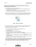
10.
Once
the
O
2
Control
Curve
is
entered,
Point
2
should
be
displayed.
Pressing
Enter
again
should
drive
the
burner
to
Point
2
if
it
is
not
already
there.
When
the
burner
is
driving
to
Point
2,
a
carat
(>)
will
be
displayed.
Once
the
burner
is
at
Point
2,
a
colon
(:)
will
be
displayed.
If
the
aux
3
actuator
is
used
for
FGR
and
FGR
‐
Mode
is
not
set
for
“Aux3onCurve”,
a
pound
(#)
indicates
the
aux
3
actuator
has
not
released
to
the
curve.
HOME
Содержание LMV 5 Series
Страница 2: ...Intentionally Left Blank ...
Страница 25: ...LMV Series Technical Instructions Document No LV5 1000 SCC Inc Page 21 Section 1 Intentionally Left Blank HOME ...
Страница 27: ...LMV Series Technical Instructions Document No LV5 1000 SCC Inc Page 23 Section 1 Intentionally Left Blank HOME ...
Страница 41: ...LMV Series Technical Instructions Document No LV5 1000 SCC Inc Page 7 Section 2 HOME ...
Страница 42: ...Technical Instructions LMV Series Document No LV5 1000 Section 2 Page 8 SCC Inc HOME ...
Страница 43: ...LMV Series Technical Instructions Document No LV5 1000 SCC Inc Page 9 Section 2 HOME ...
Страница 44: ...Technical Instructions LMV Series Document No LV5 1000 Section 2 Page 10 SCC Inc HOME ...
Страница 45: ...LMV Series Technical Instructions Document No LV5 1000 SCC Inc Page 11 Section 2 HOME ...
Страница 46: ...Technical Instructions LMV Series Document No LV5 1000 Section 2 Page 12 SCC Inc HOME ...
Страница 47: ...LMV Series Technical Instructions Document No LV5 1000 SCC Inc Page 13 Section 2 HOME ...
Страница 48: ...Technical Instructions LMV Series Document No LV5 1000 Section 2 Page 14 SCC Inc HOME ...
Страница 49: ...LMV Series Technical Instructions Document No LV5 1000 SCC Inc Page 15 Section 2 HOME ...
Страница 50: ...Technical Instructions LMV Series Document No LV5 1000 Section 2 Page 16 SCC Inc HOME ...
Страница 51: ...LMV Series Technical Instructions Document No LV5 1000 SCC Inc Page 17 Section 2 HOME ...
Страница 52: ...Technical Instructions LMV Series Document No LV5 1000 Section 2 Page 18 SCC Inc HOME ...
Страница 53: ...LMV Series Technical Instructions Document No LV5 1000 SCC Inc Page 19 Section 2 HOME ...
Страница 54: ...Technical Instructions LMV Series Document No LV5 1000 Section 2 Page 20 SCC Inc HOME ...
Страница 55: ...LMV Series Technical Instructions Document No LV5 1000 SCC Inc Page 21 Section 2 HOME ...
Страница 56: ...Technical Instructions LMV Series Document No LV5 1000 Section 2 Page 22 SCC Inc Intentionally Left Blank HOME ...
Страница 116: ...Technical Instructions LMV Series Document No LV5 1000 Section 3 Page 58 SCC Inc Intentionally Left Blank HOME ...
Страница 150: ...Technical Instructions LMV Series Document No LV5 1000 Section 4 Page 32 SCC Inc Intentionally Left Blank HOME ...
Страница 170: ...Technical Instructions LMV Series Document No LV5 1000 Section 5 Page 18 SCC Inc Intentionally Left Blank HOME ...
Страница 290: ...Technical Instructions LMV Series Document No LV5 1000 Section 8 Page 20 SCC Inc Intentionally Left Blank HOME ...
Страница 306: ...Technical Instructions LMV Series Document No LV5 1000 Section 9 Page 14 SCC Inc Intentionally Left Blank HOME ...
Страница 373: ...Intentionally Left Blank ...