
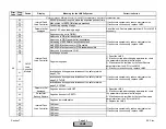
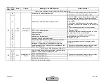
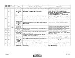
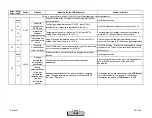

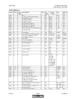
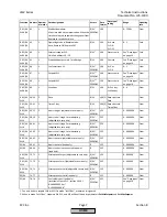
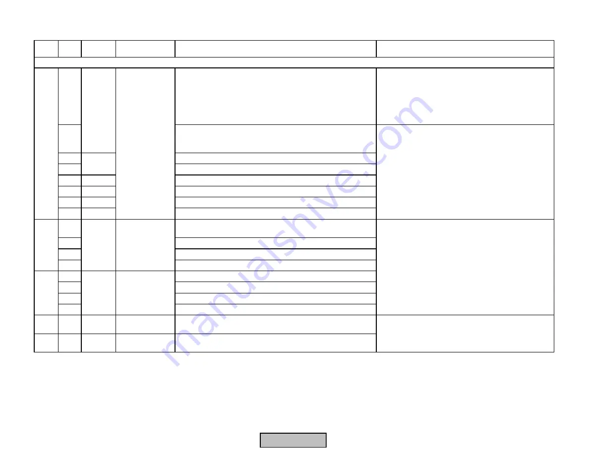
Error
Code
Diag.
Code
Device
Display
Meaning for the LMV5x System
Corrective Action
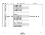
Any #
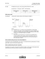
When comparing the versions of the individual units,
the AZL5 has detected old versions
Before replacing any units, start the system and wait
about 1 minute (until, after entering the parameter level,
the display “Parameters will be updated“ disappears).
Then, reset the unit. Replace the unit only if the fault
message does not disappear. Replace the relevant
units by new versions
01..2F
The diagnostic value is made up of the following faults or their
combinations (the individual diagnostic codes are added up in
hexadecimal format)
01
Software of the basic unit too old
02
Software of the load controller too old
04
AZL5
Software of the AZL5 too old
08
Actuator
Software of 1 or several actuators too old
10
LMV5
Software of VSD module too old
20
PLL5
Software of O2 module too old
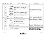
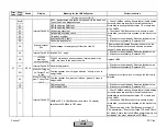
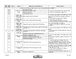
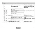
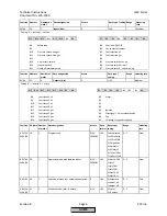
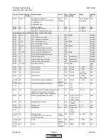
Any #
Basic unit has detected a wrong state of the VSD module.
Corresponds to the "8x"-faults with the other CAN users
01
CRC error
02
Key error main loop counter
03
No feedback for max. number
Any #
Basic unit has detected a wrong stage of the O2 module
01
CRC error
02
Key error main loop counter
03
No feedback for max. number
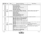
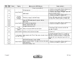
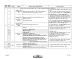
E1
Any #
LMV5
Fault Feedback
VSD Module
Basic unit has detected a ROM-CRC fault in the VSD module
when checking its feedback signal
E3
Any #
PLL5
Fault Feedback
O2 Module
Basic unit has detected a ROM-CRC fault
in the O2 module when checking its feedback signal
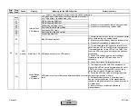
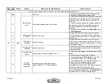
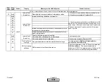
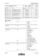
PLL5
Fault Feedback
VSD Module
LMV5
Any
1) If fault occurs sporadically: Reduce electrical noise.
2) If fault occurs constantly: Replace LMV5
3) Check CANBus cabling. Ensure that all cable shields
(screens) which are located in the cable sheath are
terminated correctly at each actuator, O2 module, and
at the LMV5x...
4) Check each CANBus connector to ensure proper
termination (no conductors exposed on the back of the
plug)
Fault Feedback
O2 Module
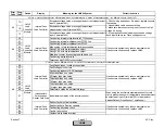
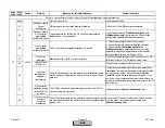
D1
D3
Version Conflict
LMV5
C5
Replace the unit(s) called out in the diagnostic code. Be
sure that the new unit has up-to-date software.
Fault with Base Unit (LMV5) or Connected Components
1) If fault occurs sporadically: Reduce electrical noise.
2) If fault occurs constantly: Replace LMV5
Section 7
Page 57
SCC Inc.
HOME
HOME
Содержание LMV 5 Series
Страница 2: ...Intentionally Left Blank ...
Страница 25: ...LMV Series Technical Instructions Document No LV5 1000 SCC Inc Page 21 Section 1 Intentionally Left Blank HOME ...
Страница 27: ...LMV Series Technical Instructions Document No LV5 1000 SCC Inc Page 23 Section 1 Intentionally Left Blank HOME ...
Страница 41: ...LMV Series Technical Instructions Document No LV5 1000 SCC Inc Page 7 Section 2 HOME ...
Страница 42: ...Technical Instructions LMV Series Document No LV5 1000 Section 2 Page 8 SCC Inc HOME ...
Страница 43: ...LMV Series Technical Instructions Document No LV5 1000 SCC Inc Page 9 Section 2 HOME ...
Страница 44: ...Technical Instructions LMV Series Document No LV5 1000 Section 2 Page 10 SCC Inc HOME ...
Страница 45: ...LMV Series Technical Instructions Document No LV5 1000 SCC Inc Page 11 Section 2 HOME ...
Страница 46: ...Technical Instructions LMV Series Document No LV5 1000 Section 2 Page 12 SCC Inc HOME ...
Страница 47: ...LMV Series Technical Instructions Document No LV5 1000 SCC Inc Page 13 Section 2 HOME ...
Страница 48: ...Technical Instructions LMV Series Document No LV5 1000 Section 2 Page 14 SCC Inc HOME ...
Страница 49: ...LMV Series Technical Instructions Document No LV5 1000 SCC Inc Page 15 Section 2 HOME ...
Страница 50: ...Technical Instructions LMV Series Document No LV5 1000 Section 2 Page 16 SCC Inc HOME ...
Страница 51: ...LMV Series Technical Instructions Document No LV5 1000 SCC Inc Page 17 Section 2 HOME ...
Страница 52: ...Technical Instructions LMV Series Document No LV5 1000 Section 2 Page 18 SCC Inc HOME ...
Страница 53: ...LMV Series Technical Instructions Document No LV5 1000 SCC Inc Page 19 Section 2 HOME ...
Страница 54: ...Technical Instructions LMV Series Document No LV5 1000 Section 2 Page 20 SCC Inc HOME ...
Страница 55: ...LMV Series Technical Instructions Document No LV5 1000 SCC Inc Page 21 Section 2 HOME ...
Страница 56: ...Technical Instructions LMV Series Document No LV5 1000 Section 2 Page 22 SCC Inc Intentionally Left Blank HOME ...
Страница 116: ...Technical Instructions LMV Series Document No LV5 1000 Section 3 Page 58 SCC Inc Intentionally Left Blank HOME ...
Страница 150: ...Technical Instructions LMV Series Document No LV5 1000 Section 4 Page 32 SCC Inc Intentionally Left Blank HOME ...
Страница 170: ...Technical Instructions LMV Series Document No LV5 1000 Section 5 Page 18 SCC Inc Intentionally Left Blank HOME ...
Страница 290: ...Technical Instructions LMV Series Document No LV5 1000 Section 8 Page 20 SCC Inc Intentionally Left Blank HOME ...
Страница 306: ...Technical Instructions LMV Series Document No LV5 1000 Section 9 Page 14 SCC Inc Intentionally Left Blank HOME ...
Страница 373: ...Intentionally Left Blank ...