

LMV
Series
Technical
Instructions
LV5
‐
1000
SCC
Inc.
Page
48
Section
3
6)
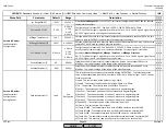
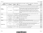
If
parameter
OilPumpCoupling
is
set
to
Magnetcoupl
,
the
output
for
the
oil
pump
can
be
energized
in
Phase
22
or
in
Phase
38,
depending
upon
how
parameter
IgnOilPumpStart
is
set.
If
parameter
OilPumpCoupling
is
set
to
DirectCoupl
,
the
output
will
energize
with
the
blower
and
de
‐
energize
15
seconds
after
the
blower
de
‐
energizes.
7)
If
gas
valve
proving
is
performed
on
startup
(immediately
after
phase
30),
the
actuators
will
be
in
prepurge
position.
If
gas
valve
proving
is
performed
on
shutdown
(immediately
after
phase
62),
the
actuators
will
be
in
the
same
position
as
they
were
in
phase
62.
The
actuators
will
not
move
during
valve
proving.
8)
If
parameter
AirPressureTest
is
set
to
activated
,
the
air
pressure
switch
must
open
after
postpurge
is
complete,
causing
input
terminal
X3
‐
02.1
to
de
‐
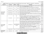
energize.
The
LMV5
will
wait
about
30
seconds
in
phase
10
(driving
to
home
position)
for
the
switch
to
open
before
the
LMV5
goes
into
alarm.
This
is
done
to
check
for
welded
contacts
in
the
air
pressure
switch.
If
air
pressure
switch
alarms
are
encountered
in
phase
10,
increasing
the
setpoint
of
the
air
pressure
switch
typically
cures
this
problem.
If
AirPressureTest
is
set
to
deactInStby
,
the
air
pressure
switch
is
not
checked
in
phase
10
or
12,
but
the
switch
must
be
open
or
the
LMV5
will
not
start
when
it
receives
a
call
for
heat.
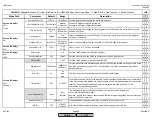
9)
The
LMV5
can
be
configured
for
different
reactions
to
extraneous
light
(a
flame
signal
when
there
should
not
be
one).
Depending
on
how
parameters
ReacExtranLight
and
ExtranLightTest
are
configured,
the
LMV5
can
lockout,
block
the
startup
sequence,
or
ignore
it
altogether.
The
extraneous
light
test
should
always
be
enabled
for
gas
/
oil
fired
boilers.
The
only
time
parameter
ExtranLightTest
should
be
set
to
deactivated
is
for
applications
such
as
waste
incineration.
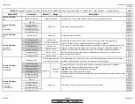
10)
If
direct
start
is
enabled
and
there
is
a
call
for
heat
after
phase
62,
the
LMV5
will
omit
phase
78
and
will
go
to
phase
79.
In
phase
79,
the
LMV5
will
check
the
blower
air
pressure
switch
with
the
blower
still
running
by
using
a
three
‐
way
solenoid
valve
(APS
checking).
If
the
switch
checks
out,
the
LMV5
will
then
proceed
directly
to
phase
24
(driving
to
prepurge
position).
11)
Safety
Time
1
is
defined
as
the
overlap
of
the
ignition
spark
and
pilot
valve.
Safety
Time
2
is
defined
as
the
overlap
of
the
pilot
valve
and
the
main
fuel
valves.
Interval
1
and
Interval
2
are
stabilization
times
for
the
pilot
and
main
flames,
respectively.
12)
If
parameter
ContinuousPurge
is
set
to
activated,
fan
output
X3
‐
01.1
will
be
energized
in
all
phases.
Typically
this
is
used
in
burner
applications
where
return
heat
may
be
a
problem.
HOMEHOME
Содержание LMV 5 Series
Страница 2: ...Intentionally Left Blank ...
Страница 25: ...LMV Series Technical Instructions Document No LV5 1000 SCC Inc Page 21 Section 1 Intentionally Left Blank HOME ...
Страница 27: ...LMV Series Technical Instructions Document No LV5 1000 SCC Inc Page 23 Section 1 Intentionally Left Blank HOME ...
Страница 41: ...LMV Series Technical Instructions Document No LV5 1000 SCC Inc Page 7 Section 2 HOME ...
Страница 42: ...Technical Instructions LMV Series Document No LV5 1000 Section 2 Page 8 SCC Inc HOME ...
Страница 43: ...LMV Series Technical Instructions Document No LV5 1000 SCC Inc Page 9 Section 2 HOME ...
Страница 44: ...Technical Instructions LMV Series Document No LV5 1000 Section 2 Page 10 SCC Inc HOME ...
Страница 45: ...LMV Series Technical Instructions Document No LV5 1000 SCC Inc Page 11 Section 2 HOME ...
Страница 46: ...Technical Instructions LMV Series Document No LV5 1000 Section 2 Page 12 SCC Inc HOME ...
Страница 47: ...LMV Series Technical Instructions Document No LV5 1000 SCC Inc Page 13 Section 2 HOME ...
Страница 48: ...Technical Instructions LMV Series Document No LV5 1000 Section 2 Page 14 SCC Inc HOME ...
Страница 49: ...LMV Series Technical Instructions Document No LV5 1000 SCC Inc Page 15 Section 2 HOME ...
Страница 50: ...Technical Instructions LMV Series Document No LV5 1000 Section 2 Page 16 SCC Inc HOME ...
Страница 51: ...LMV Series Technical Instructions Document No LV5 1000 SCC Inc Page 17 Section 2 HOME ...
Страница 52: ...Technical Instructions LMV Series Document No LV5 1000 Section 2 Page 18 SCC Inc HOME ...
Страница 53: ...LMV Series Technical Instructions Document No LV5 1000 SCC Inc Page 19 Section 2 HOME ...
Страница 54: ...Technical Instructions LMV Series Document No LV5 1000 Section 2 Page 20 SCC Inc HOME ...
Страница 55: ...LMV Series Technical Instructions Document No LV5 1000 SCC Inc Page 21 Section 2 HOME ...
Страница 56: ...Technical Instructions LMV Series Document No LV5 1000 Section 2 Page 22 SCC Inc Intentionally Left Blank HOME ...
Страница 116: ...Technical Instructions LMV Series Document No LV5 1000 Section 3 Page 58 SCC Inc Intentionally Left Blank HOME ...
Страница 150: ...Technical Instructions LMV Series Document No LV5 1000 Section 4 Page 32 SCC Inc Intentionally Left Blank HOME ...
Страница 170: ...Technical Instructions LMV Series Document No LV5 1000 Section 5 Page 18 SCC Inc Intentionally Left Blank HOME ...
Страница 290: ...Technical Instructions LMV Series Document No LV5 1000 Section 8 Page 20 SCC Inc Intentionally Left Blank HOME ...
Страница 306: ...Technical Instructions LMV Series Document No LV5 1000 Section 9 Page 14 SCC Inc Intentionally Left Blank HOME ...
Страница 373: ...Intentionally Left Blank ...