background image

23-31

Computer Link

23

(2) Using memory

To allow the memory to be used by the IV-C35M, enter a result write start address within the following
setting range.

Note: The IV-C35M uses [DM area write] command of C mode command. Concerning the limitation

of address settings, see OMRON's PC manual.

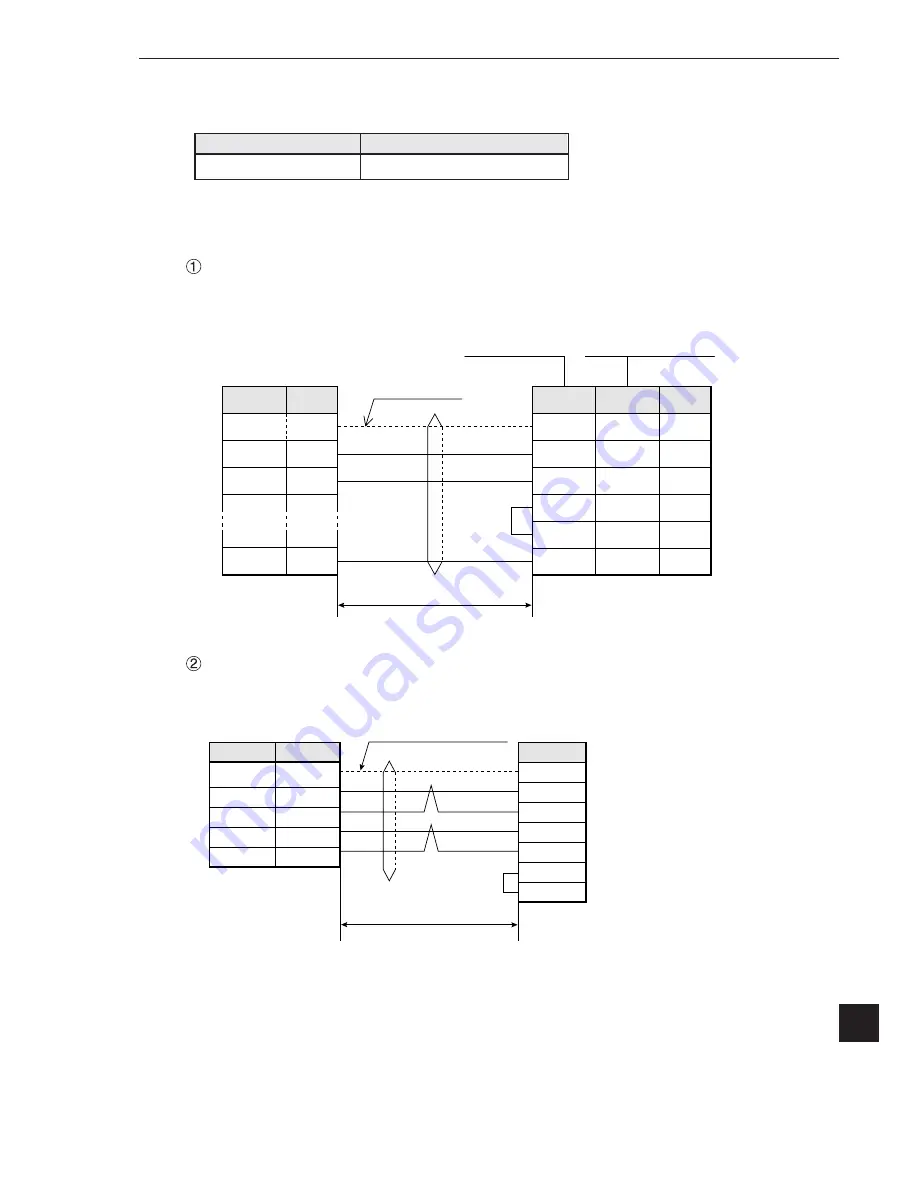
(3) Connections


Example of RS-232C communication

 Example of RS-422 communication

FG

RD

SD

SG

2

3

5

FG

SD

RD

RS

CS

SG

1

2

3

4

5

7

Connector 

hood

2

3

4

5

9

C500-LK203

C200-LK201

CV500-LK201

(Communication port 1)

CV500-LK201

(Communication port 2)

CV CPU module

15m or less

RS-232C

Shielded cable

Communication connector on 
the IV-C35M (RS232C/RS422)

Pin No. 

Signal 

name

Pin No. 

Pin No. 

Signal 

name

Connector

shield

FG

SDB(SD+)

SDA(SD-)

RDB(RD+)

RDB(RD-)

RS

CS

Calculator link
module

FG

TA

TB

RA

SG

Connector

shield

4

7

8

9

IV-C35M communication
connector
(RS232C/RS422)

1 km max.

RS-422 (4-line system) 

Shielded, twisted-pair cable

Pin No. 

Signal name

Signal name

Pin numbers vary with
the module to be used

Memory

D (data register)

Range (address)

0 to 9999

Содержание IV-C35M

Страница 1: ...User s Manual Function and Operation Compact Color Image Sensor Camera Version 1 0 Produced in July 2002 ...

Страница 2: ...ral performance specifications Example of operation and instruction Become acquainted with the IV C35M Learn how to install the IV C35M and wire it up When mastering the outline of operation IV C35M User s manual Function and Operation Detailed explanations of all the measurement functions How to make menu selections for each measurement Details of inputting and outputting data and communications ...

Страница 3: ...Outline Chapter 2 Setting the Operating and System Conditions Chapter 3 Setting Measurement Conditions Chapter 4 Positional Deviation Measurement Chapter 5 Degree of Match Inspection Chapter 6 Lead Inspection Chapter 7 BGA CSP Inspection Chapter 8 Area Measurement by Binary Conversion Chapter 9 Object Counting by Binary Conversion Chapter 10 Object Identification by Binary Conversion Chapter 11 Co...

Страница 4: ... display NG images 1 19 3 Initializing the NG images 1 23 1 9 Operation flow 1 24 1 Power ON and main loop processing 1 24 2 Operation flow after the measurement start input is turned ON 1 26 1 10 Table of controller functions 1 29 Chapter 2 Setting the Operating and System Conditions 2 1 to 2 23 2 1 Setting the operating conditions 2 1 1 Monitor output 2 2 2 Image capture 2 4 3 Message display 2 ...

Страница 5: ...r 3 48 2 Setting the shutter speed 3 50 3 Copying 3 51 4 NG image registration 3 52 5 Halt on NG measurement 3 53 6 Window group move 3 54 Chapter 4 Positional Deviation Measurement 4 1 to 4 14 4 1 Outline 4 1 4 2 Setting operation 4 2 1 Setting the register conditions for a gray search 4 5 2 Setting the register conditions for edge detection 4 8 Chapter 5 Degree of Match Inspection 5 1 to 5 9 5 1...

Страница 6: ...ion 14 2 Chapter 15 Multiple Positional Measurements 15 1 to 15 11 15 1 Outline 15 1 15 2 Setting operation 15 2 1 Setting the register conditions for a gray search 15 5 2 Setting the register conditions for edge detection 15 7 Chapter 16 Multiple Degree of Match Inspection 16 1 to 16 8 16 1 Outline 16 1 16 2 Setting operation 16 2 Chapter 17 Fault Inspection 17 1 to 17 7 17 1 Outline 17 1 17 2 Se...

Страница 7: ...tput block assignment Computer link output and general purpose serial output 21 25 1 Data in specified blocks 21 25 2 Setting operating procedure 21 26 21 7 Setting the data output 21 28 1 Select ANY for the serial output 21 28 2 Select YES or NO for output data 21 29 21 8 Calibrating the IV C35M 21 30 Chapter 22 Communication General Purpose Serial Interface 22 1 to 22 17 22 1 List of processing ...

Страница 8: ...s for the IV C35M 23 20 2 Connection with a Sharp PC 23 21 3 Connection with a Mitsubishi PC 23 27 4 Connection with an OMRON PC 23 30 23 7 Program examples 23 32 Chapter 24 Troubleshooting 24 1 to 24 6 1 Symptoms and checks 24 1 2 Causes of termination codes when an error occurs and remedies 24 3 3 Causes and treatments for error messages 24 5 4 Maintenance 24 6 ...

Страница 9: ...6 8 Option 2 Installation assembly Install the hardware you will be using Connection of cameras and monitor to the controller Installation of the controller and camera body Connection of a power supply input output terminals and external devices Supply power to each device 3 Turning ON the power supply controller and monitor 5 Enter measuring programs 6 Editing Operation screen 7 Other settings 8 ...

Страница 10: ...TITLE YES End 1 2 Method for selecting the menu configuration 1 Set wizard The IV C35M has a Set Wizard function to assist beginners in setting the measurement conditions Select SET WIZARD from the MAIN MENU and the wizard will show the items needed for each step You only need to make selections according the instructions on the screen Using the wizard you can establish the minimum required settin...

Страница 11: ...ed When is shown it means that the lower menu level is already open OBJECT TYPE COND TYPE00 TYPE01 TYPE RUN COND IMAGE ADJ MEA CND CAMERA1 MEAS0 POSI DEVIATION POSI CORRECT MEAS01 MEAS BIN AREA F MEAS NEW MEA CND CAMERA2 FINAL NUM CALC FINAL OUTPUT COND OBJ TYPE I 0 OBJ TYPE SYS TYPE NEW OBJECT TYPE COND TYPE00 TYPE01 TYPE RUN COND IMAGE ADJ MEA CND CAMERA1 MEAS0 POSI DEVIATION POSI CORRECT MEAS01...

Страница 12: ...CAMERA2 FINAL NUM CALC FINAL OUTPUT COND OBJ TYPE I O OBJ TYPE SYS TYPE00 I O CONDITIONS COMM SET COMPUTER LINK GAIN OFFSET TIME CAMERA TYPE TYPE31 1CHG TYPE 2STANDARD WIZARD 3OPERATION CHART MAIN OPS MENU 1INITIALIZATION 2SELF DIAGNOSIS 1 MEAS0 POSI DEVIATION POSI CORRECT MEAS01 MEAS02 MEAS03 2 MEAS04 IMG PRE PROC MEAS CND EVALUATION COND DISTANCE ANGLE COND NUM CALC OUT COND REG COND S REG COND ...

Страница 13: ...umber top line of the written results Gain offset 2 15 System time 2 16 Camera setting 2 17 Camera selection image capture mode Same for Camera 1 and 2 However Measurement 0 Camera 2 is not available Measurement 0 camera 1 Measurement 0 camera 2 Measurement 1 Measurement 2 Measurement 3 Measurement 4 Image pre processing 3 20 Input and output for each object type System for each object Measuring p...

Страница 14: ...P3 STEP3 SELECT A COLOR IMAGE PROCESSING MODE 1COLOR FILTER 2EXTRACT COLOR COLOR FILTER SET DETAIL SELECT A MEASUREMENT TYPE 1MEAS SEL POSI DEVIATION RETURN NEXT SET WIZARD SCREEN SAVE DEL F C1 BRT SAMPLE 1CHG TYPE 2STANDARD WIZARD 3OPERATION CHART TYPE00 Start End When DETAIL is selected When 2CAM1 or 3CAM2 is selected 1COMM STANDARD RS232C 2BAUDRATE kdps 115 2 3NO OF DATA BITS 7BIT 4PARITY CHECK...

Страница 15: ...MAGE PROCESSING 1NO 2GRAY SRC 3EDGE DTECT 4SCH EDGE 1NUM OF DTECT 1P ENTER A RANGE AND UNITS FOR ROTATION ANGLE DETECTION 1DTECT ANGL NO RETURN NEXT DETAIL STEP4 SELECT TYPE OF CALCUATION BETWEEN IMAGES 1COMPARE IMGS NO SELECT WHETHER OR NOT TO CONVERT IMGE DENSITY 1CHNG GRAY LEVELNO SELECT FILTER TYPE FOR IMAGE DATA 1SPACE FILTER NO RETERN NEXT DETAIL 1REGISTER NO 0 0 7 2MEAS SHAPE MDL0 RECTANGLE...

Страница 16: ...SULTS YES NO 1NO 2YES MEAS 3YES DST AGL RETURN NEXT DETAIL DETAIL STEP8 LADDER CIRCUIT AND RESULT OUTPUT BASED ON MESUREMENT AND CALCULATION RESULTS YES NO 1NO 2YES MEAS 3YES DST AGL RETURN NEXT DETAIL DETAIL STEP8 ADD MEASUREMENT CONDITIONS 1NO 2YES RETURN NEXT STEP8 INPUT00 07 CHANGE INPUT 0 1 2 3 4 5 6 7 OUT INPUT00 LOGIC INPUT02 LOGIC INPUT03 STEP8 USE SETTING DISTANCE ANGLE CONDITIONS YES NO ...

Страница 17: ...N NO 00 0 7F TYPE RUN COND SCREEN SAVE 1MONITOR OUTPUT CAM1 2CAPTURE IMG PARIAL IMG 3MESSAGE DISPLAY YES NUMERIC 4PATTERN DISPLAY YES 5SHOW BINARY IMG YES 6SHOW FIX IMG YES 7OPS MAIN DISP YES 8DISP CHG EVAL NO 9PC MNTR NO 0THROUCH DISPLAY NO qEXTENSION FUNC NO CHANGE DISPLY CONTENTS OF THE MAIN OPS MENU 1NO 2YES RETURN NEXT DETAIL STEP8 SET LADDER CIRCUIT RESULT OUTPUT BASED ON ALL MEASUREMENT AND...

Страница 18: ...g time 9 I O relay 3 Freeze through screen 4 Camera currently selected 5 Image brightness bright dark 6 Software version q Menu display TYPE00 COLOR F C1 BRT V MEAS 0000ms 2001 10 14 10 38 X0 7 Y0 7 READY MNU CHG MAIN COND CHG MEA COND CHG CHGN REG SCREEN CHG CHGTYPE MEASURE 0 CAM1 NO 8 Measurement setting details 2 Color mode y a l p s i D d o h t e m n o i t p i r c s e D h g u o r h T e g a m i...

Страница 19: ...ows When this menu is selected the second row will appear The details of each item on this menu bar are shown on the next page Serial communication time is not included Set the controller as follows to reduce the measurement time 1 Increase the shutter speed 2 Select the partial image capture feature for the CCD 3 Select NO for the measurement results display message display pattern display and bi...

Страница 20: ... This is enabled when Manual Object Type Change is set to YES NEXT NG change the NG image List the NG screens that can be selected Select a screen using the up and down keys CHG C1 change the Camera 1 image position Moves the image from Camera 1 up and down the screen using the up and down arrow keys Note This is enabled when CAM1 2 or CAM1 NG IMG is selected in 1MONITOR OUTPUT on the TYPE RUN CON...

Страница 21: ...nd press the SET key 3 Move the cursor to the TYPE NEW item on the OBJECT TYPE COND line and press the SET key 4 Move the cursor to TYPE00 on the SELECT OBJECT TYPE COND line and press the SET key To select TYPE01 and others move the cursor to TYPE NEW and press the SET key 5 Select MEAS0 to 4 MEAS0 is only used for positional deviation measurements on the MEAS COND CAM1 line and a popup menu will...

Страница 22: ...cursor to SAVE using the up down and left right keys and press the SET key The following message will be displayed on the lower part of the screen DATA SAVE Do you want to save the data YES SET NO ESC 2 Press the SET key The IV C35M will start saving the data and the progress will be displayed on the bottom of the screen When the data has been saved in the IV C35M flash memory the display will cha...

Страница 23: ...llow the procedure described below when turning ON the power to the controller IV C35M and the POWER ON SETTING menu will be displayed on the monitor 1 Turn ON the power to the IV C35M controller while holding down the ESC key 2 Keep pressing the ESC key down for approx 9 sec after turning ON the power and the menu will be displayed Operation procedure 1 On the POWER ON SETTING menu move the curso...

Страница 24: ...surement is triggered Direction keys up down left and right SET key ESC key SEL key TRG BRT key 1 2 3 4 5 Select an item with the up down left and right keys The direction keys have an auto repeat function Set each coordinate Setting a window Returning a setting to its original state before be ing changed Returning to the previous menu Determine a highlighted item Use to select the display of obje...

Страница 25: ... 52 NG screen setting procedure On the SELECT OBJECT TYPE COND screen select MEA CND CAMERA2 and press the TRG BRT key From the popup menu select NG IMGS and press the SET key When the message shown on the right appears press the SET key SET TO NEXT SUB MENU ESC BACK SEL CHNG IMG TRG POPUP COLOR F C1 BRT OBJECT TYPE COND TYPE00 TYPE RUN COND IMAGE ADJ MEA CND CAMERA1 MEA CND CAMERA2 FINAL NUM CALC...

Страница 26: ...can be registered at one time the NG image numbers are 0 to 127 When 128 NG images are registered the oldest NG image will be deleted and replaced by the 129th NG image All of numbers assigned to the NG images will de decrement by one The actual total number of NG images that can be registered may less than the 128 depending on the size of the images registered Limitation The total number of NG im...

Страница 27: ... NG image display screen See page 1 22 The setting procedures are as follows 1 Select CAM1 NG IMG from the monitor output See page 1 17 to 1 18 2 Set the monitor output to NG IMGS or CAM1 NG IMG Select MONITOR OUTPUT on the TYPE RUN COND menu Description MONITOR OUTPUT CAM1 NG IMGS CAM1 NG IMG HORIZ CAM1 NG IMG VERT Display the camera 1 image on the whole screen Display the NG image on the whole s...

Страница 28: ...splay camera1 measured image Display camera1 NG image MNU CHG MAIN COND CHG MEA COND CHG CHNG REG SCREEN CHG CHG TYPE COLOR C2 BRT V TYPE00 Display example when the monitor output is set to NG IMG Display camera1 NG image MNU CHG MAIN COND CHG MEA COND CHG CHNG REG SCREEN CHG CHG TYPE MNU CHG MAIN COND CHG MEA COND CHG CHNG REG SCREEN CHG CHG TYPE 3 Return to the operation main screen page 1 10 an...

Страница 29: ...An example of the split screen display above and below Display history of NG images Move the cursor to the menu bar SCREEN CHG on the operation main screen using the left and right key Select the NG IMG DISP from the popup menu to display previous NG images An example of scrolling the split screen display above and below When a new NG image is captured while displaying the history it will be added...

Страница 30: ...umbers using the up and down keys MEASURE0 CAM1 MEASURE0 CAM2 MEASUREMENT1 MEASUREMENT2 MEASUREMENT3 MEASUREMENT4 COND CHG change measurement condition Change the operation menu using the up and down keys Display NG image change evaluation conditions The operating screen display must be set to YES See page 2 9 For information about the evaluation condition change screen see page 2 11 On the evalua...

Страница 31: ... the stored NG images have the maximum rectangular area set by measurements 0 to 4 3 Initializing the NG images NG images can be initialized with any of the following methods 1 Item INITIALIZATION on the OPTION menu will execute an NG IMG INIT Page 2 20 2 Execute a DEL NG delete NG image or DEL ALL N delete all NG images on the menu bar of the NG image display screen See the previous page 3 When t...

Страница 32: ...itions specified for each object type Power ON Data setting CPU variables Gate array Obtaining images capturing specific lines of an image To the next page ESC key Display check sum results Checksum checking Settings for all types completed Initializing CPU gate array Wait to complete the power ON process Transmitting from flash memory to RAM Transmitting from flash memory to RAM Memory check Plac...

Страница 33: ...e serial Main loop processing From the preceding page Measurement result output processing Executing measurements Communication processing Data received Key input Communication processing Measurement start PC calculation PC calculation Message display Pattern display Crosshair cursor display Receive a measurement start input signal Process key strokes Processing on sub menu Menu configuration See ...

Страница 34: ...rror detected 1 To the next page 2 To the next page Executing measurement 0 using camera 2 Executing measurement 0 using camera 1 Measurement timer start Reading the object type No Image capturing camera 1 2 Measurement program that is selected Positional deviation measurement Capture the scan line range that was specified when setting the measurement conditions 1 The measurement start input is se...

Страница 35: ...f match inspection Lead inspection BGA CSP inspection Area measurement by binary conversion Counting by binary conversion Object identification by binary conversion Color evaluation Color unevenness inspection Color positional measurement Point measurement Multiple positional measurements Multiple degree of match inspection Fault inspection 1 From the preceding page 2 From the preceding page Yes Y...

Страница 36: ... time timer stop Serial output General purpose serial output Computer link output Waiting for a measurement start input signal or a key input From the previous page 3 3 Set the measurement start input to any choice other than parallel or set the READY ON signal to end measurement No Yes READY ON When the stop NG measurement option is set to YES page 3 53 the controller stops measuring when an erro...

Страница 37: ...64 64 pixels and the contraction function is set to 3 Gray search edge detection precision Pixel sub pixel Image processing Color filter R G B brightness custom Color extraction hue saturation brightness Gray search Color image pre processing Hue correction Adjust hue level Brightness correction Adjust brightness level Gray image pre processing Shading correction Dividing subtracting and filtering...

Страница 38: ...of match XY coordinate 1 point search 1 point edge Maximum 4 windows Multiple degree of match inspection Number of objects max 128 degree of match XY coordinate 1 point search Maximum 4 windows Number of measurement programs Maximum 6 per object type measurement 0 camera 1 measurement 0 camera 2 measurements 1 to 4 Note Measurement 0 is only used for positional deviation measurement Window shape R...

Страница 39: ...se serial I F keypad trigger for manual measuring Inputs Number of points 8 points External trigger 1 point X0 Object type change 5 points X1 to X5 external input 2 points X6 X7 Common terminal 1 point or common Outputs Number of points 9 points 1 READY 8 user settable logical outputs Y0 to Y7 Common terminal 1 point or common Power supply Power supply terminal 2 points 24 VDC 0 V Power supply vol...

Страница 40: ... i t a u l a v E 0 1 2 n e e r c s r o t i n o m C P 1 1 2 y a l p s i d h g u o r h T 1 1 2 n o i t c n u f n o i s n e t x E 2 1 2 OBJECT TYPE COND TYPE00 TYPE RUN COND IMAGE ADJ MEA CND CAMERA1 MEA CND CAMERA2 FINAL NUM CALC FINAL OUTPUT COND OBJ TYPE I O OBJ TYPE SYS TYPE NEW SELECT OBJECT TYPE COND COLOR F C1 BRT 1MONITOR OUTPUT 2CAPTURE IMG 3MESSAGE DISPLAY 4PATTERN DISPLAY 5SHOW BINARY IMG ...

Страница 41: ...NARY IMG YES 6SHOW θ FIX IMG YES 7OPS MAIN DISP YES 8DISP CHG EVAL NO 9PC MNTR NO 0THROUGH DISPLAY NO qEXTENSION FUNC NO TYPE RUN COND SCREEN SAVE COLOR F C1 BRT SET SELECT A MENU ESC BACK SEL CHNG IMG TRG FUNC CAM1 CAM2 CAM1 2 HORIZ CAM1 2 VERT SERIAL NO 8F053G26 MODEL IV C35M COLOR F C2 H SERIAL NO 8F053G26 MODEL IV C35M SERIAL NO 8F053G26 MODEL IV C35M Simultaneous display on a divided screen W...

Страница 42: ...AS INP I F PARALLEL SERIAL USB 2OUT I F PARAL NO 3MANL TYPE CHNG NO 4PARALLEL INP X6 EXT INP 5PARALLEL INP X7 CHNG IMG OUT CAM 6STROBE OUT NO 7 READY ON CAPTURE COMPLETE I O CONDITION SCREEN COND SAVE COLOR F C1 BRT SET SELECT A MENU ESC BACK SEL CHNG IMG TRG FUNC EXT INP CHNG IMG OUT CAM CAM MEAS Every time the X7 signal is turned from OFF to ON the selected camera display will be changed CAM1 wh...

Страница 43: ...ere are 240 scan lines 1MONITOR OUTPUT CAM1 2CAPTURE IMG PARTIAL IMG 3MESSAGE DISPLAY YES NUMERIC 4PATTERN DISPLAY YES 5SHOW BINARY IMG YES 6SHOW θ FIX IMG YES 7OPS MAIN DISP YES 8DISP CHG EVAL NO 9PC MNTR NO 0THROUGH DISPLAY NO qEXTENSION FUNC NO TYPE RUN COND SCREEN SAVE COLOR F C1 BRT PARTIAL IMG WHOLE IMG NO PARTIAL IMG partial image WHOLE IMG whole image NO no image Description 2CAPTURE IMG N...

Страница 44: ...he SET key When NO is selected The menu bar will be displayed COLOR F C1 DRK V TYPE00 AREA1 OK MEAS XXXXms XXXX XX XX XX XX MEASURE 0 CAM1 POSI DEVIATION X0 7 Y0 7 READY REGST NO 0 0 7 X0 176 0 OK Y0 322 0 OK x0 000 0 OK y0 000 0 OK M0 10000 OK B0 001 7 OK X1 534 0 OK Y1 480 0 OK x1 001 0 OK y1 001 0 OK M1 09999 OK COLOR F C1 DRK V TYPE00 AREA1 OK MEAS XXXXms XXXX XX XX XX XX MEASURE 0 CAM1 POSI D...

Страница 45: ...RE 0 CAM1 POSI DEVIATION X0 7 Y0 7 READY REGST NO 0 0 7 X0 176 0 OK Y0 322 0 OK x0 000 0 OK y0 000 0 OK M0 10000 OK B0 001 7 OK X1 534 0 OK Y1 480 0 OK x1 001 0 OK y1 001 0 OK M1 09999 OK When YES is selected for PATTERN DISPLAY When NO is selected for PATTERN DISPLAY MNU CHG MAIN COND CHG MEA COND CHG CHNG REG SCREEN CHG CHG TYPE MNU CHG MAIN COND CHG MEA COND CHG CHNG REG SCREEN CHG CHG TYPE 1MO...

Страница 46: ...LOR F C1 DRK VX XX When YES is selected for the 5SHOW BINARY IMG When NO is selected for the 5SHOW BINARY IMG MEAS XXXXms XXXX XX XX XX XX MEASUREMENT1 CNT BIN OBJ MEAS XXXXms XXXX XX XX XX XX MEASUREMENT1 CNT BIN OBJ MNU CHG MAIN COND CHG MEA COND CHG CHNG REG SCREEN CHG CHG TYPE MNU CHG MAIN COND CHG MEA COND CHG CHNG REG SCREEN CHG CHG TYPE 1MONITOR OUTPUT CAM1 2CAPTURE IMG PARTIAL IMG 3MESSAGE...

Страница 47: ... IMG TRG FUNC YES NO YES NO A q angle corrected image will be displayed on the operation screen A q angle corrected image will not be displayed on the operation screen Description SHOW FIX q IMG Reference image Measured image Position of reference image When the qangle correction image display mode has been set to YES When the q angle correction image display mode has been set to NO 1MONITOR OUTPU...

Страница 48: ... MAIN line is highlighted press the SET key The main display will then change back to the operation screen from the other screens e g the JDG COND CHG and PC MNTR screens 1MONITOR OUTPUT CAM1 2CAPTURE IMG PARTIAL IMG 3MESSAGE DISPLAY YES NUMERIC 4PATTERN DISPLAY YES 5SHOW BINARY IMG YES 6SHOW θ FIX IMG YES 7OPS MAIN DISP YES 8DISP CHG EVAL NO 9PC MNTR NO 0THROUGH DISPLAY NO qEXTENSION FUNC NO TYPE...

Страница 49: ...me the screen display will look the same as the normal operation main screen except for the area marked evaluation condition change menu shown during operation 1MONITOR OUTPUT CAM1 2CAPTURE IMG PARTIAL IMG 3MESSAGE DISPLAY YES NUMERIC 4PATTERN DISPLAY YES 5SHOW BINARY IMG YES 6SHOW θ FIX IMG YES 7OPS MAIN DISP YES 8DISP CHG EVAL YES 9PC MNTR NO 0THROUGH DISPLAY NO qEXTENSION FUNC NO TYPE RUN COND ...

Страница 50: ...SET CN7 NOT SET MMU CHG MAIN COND SEL OUT SEL AUX SEL NUM SCREEN CHG CHG TYPE NO YES Description THROUGH DISPLAY Measurements can be made on a through image Measurements can be made on a frozen image 1MONITOR OUTPUT CAM1 2CAPTURE IMG PARTIAL IMG 3MESSAGE DISPLAY YES NUMERIC 4PATTERN DISPLAY YES 5SHOW BINARY IMG YES 6SHOW θ FIX IMG YES 7OPS MAIN DISP YES 8DISP CHG EVAL NO 9PC MNTR NO 0THROUGH DISPL...

Страница 51: ...rsor using the up down left right arrow keys It moves one pixel at a time 5 When the cursor is positioned where you want it press the SET key to confirm the position If you select DISPLAY CURSOR 2 you can display two cursors when you output monitor images from Cameras 1 and 2 NO DISPLAY CURSOR MANL MEAS 1MONITOR OUTPUT CAM1 2CAPTURE IMG PARTIAL IMG 3MESSAGE DISPLAY YES NUMERIC 4PATTERN DISPLAY YES...

Страница 52: ...move one pixel at a time The distance between the two points and between the X coordinates and Y coordinates for the two points will change on real time basis 8 After the positions of the points are determined press the SET key 9 When the operation is complete press the ESC key The manual measurement menu items will disappear 1MONITOR OUTPUT CAM1 2CAPTURE IMG PARTIAL IMG 3MESSAGE DISPLAY YES NUMER...

Страница 53: ...he 3MANL TYPE CHNG is set to YES the type cannot be changed with an external interface parallel I O or general purpose serial interface YES NO Description MANL TYPE CHNG The type cannot be manually changed on the operation screen MAIN MENU COLOR F C1 BRT IVC35M SYS CND OBJECT TYPE COND SET WIZARD EDIT MAIN OPS MENU OPTION ENVIRONMENT SETTING MEMORY CARD SET TO NEXT SUB MENU ESC BACK SEL CHNG IMG T...

Страница 54: ...ction The offset for camera 1 is adjusted with the up and down keys The complete signal level is shifted leaving the amplitude of the image signals from the CCD camera unchanged As the offset value is increased the whole screen will becomes more white The gain for camera 1 is adjusted with the up and down keys The amplitude of the image signals from the CCD camera is changed As the gain value is r...

Страница 55: ...g procedure 1 Select TIME on the SYS CND menu and press the SET key 2 Move the cursor to Minute Day Hour Month and Year using the left and right keys and enter the correct value at each location using the up and down keys Y 1999 to 2098 M 01 to 12 D 01 to 31 H 00 to 23 MIN 00 to 59 3 Press the SET key The time will be set and the system will start using the new time 1TIME 2001 10 24 15 29 TIME SCR...

Страница 56: ...ochrome camera is used SELECT CAMERA Select MONOCHROME from the popup menu CAPTURE IMG MODE Select image capture mode from FULL HALF or FLL HALF Compatible cameras IV C30C5 color camera IV S30C3 high speed monochrome camera IV S30C4 micro high speed monochrome camera Compatible cameras IV C30C5 color IV S30C3 high speed IV S30C4 micro and high speed Camera settings system conditions Camera selecti...

Страница 57: ...i l d e i f i c e p s e h t y l n o r e f s n a r T a e r a e d o m l l u f a e r a d e i f i c e p s e h t t c e r r o C r e f s n a r t d n a l l i w e g a m i e n i l n e v e e h T e h t y b d e t n e m e l p p u s e b e g a m i e n i l d d o p u g n i t t e s r o f s s e c o r P n e e r c s e h t e h t f o l l a t u P a e r a e n i l d e r u t p a c e d o m l l u f e h t n i e h t f o l l a t ...

Страница 58: ... position press the SET key again Note If you do not press the SET key lastly the movement is not executed MAGNIFICATION REDUCTION Move the cursor to the MAGNIFCATION or REDUCTION line and press the SET key The highlighted block of text can be enlarged or reduced Selectable sizes are two enlarge standard reduced standard NON DISP Move the cursor to the NON DISP line and press the SET key The highl...

Страница 59: ...T key twice The controller will execute a self diagnosis and display the results of the diagnosis as shown right If the diagnosis results are normal OK will be displayed If the results are abnormal NO will be displayed When the diagnosis is complete the DIAGNOSING display will change to COMPLETE DIAGNOSIS COLOR F C1 BRT MAIN MENU SET TO NEXT SUB MENU ESC BACK SEL CHNG IMG TRG POPUP IVC35M SYS CND ...

Страница 60: ...TION ENVIRONMENT SETTING MEMORY CARD Display items Available colors 1OBJ TYPE NO TITLE 0 black 7 white 2FIN EVAL RESULT OK 0 black 1 red 4 blue 7 white 3FIN EVAL RESULT NG 0 black 1 red 4 blue 7 white 4MEAS EVAL RESULT OK 0 black 7 white 5MEAS EVAL RESULT NG 0 black 7 white 6ERROR MESSAGE 0 black 7 white 7DISP A MENU NORMAL 0 black 7 white 8DISP A MENU SELECTED 0 black 7 white 9BIN IMAGE NORMAL 0 ...

Страница 61: ...B MENU using the up and down arrow keys and press the SET key INPUT FILE NAME screen will appear Enter FILE NAME and COMMENT on this screen Note To move the cursor from the FILE NAME block to the COMMENT box select the down arrow key on the screen and press the SET key COLOR F C1 BRT MAIN MENU SET TO NEXT SUB MENU ESC BACK SEL CHNG IMG TRG POPUP IVC35M SYS CND OBJECT TYPE COND SET WIZARD EDIT MAIN...

Страница 62: ...TYPE line EXEC Select EXEC and press the SET key A screen shown below will appear UNDER ACCESS Note When SAVE AS is selected UNDER ACCESS will appear on the screen 1TRANSMISSION METHOD 2INPUT FILE NAME 3FILE TYPE FILE NAME 4EXEC SET KEY COLOR F C1 BRT MEMORY CARD SCREEN SAVE NEW SAVE TO NEXT SUB MENU PARAM PARAM NG IMG 1TRANSMISSION METHOD 2SELECT FILE FILE TYPE FILE NAME 3EXEC COLOR F C1 BRT MEMO...

Страница 63: ...ement programs are allocated to MEAS01 through MEAS04 The smallest measurement number available from 1 to 4 will be assigned MEAS0 is dedicated to positional deviation measurements OBJECT TYPE COND TYPE00 TYPE01 TYPE02 TYPE03 TYPE04 TYPE05 TYPE NEW SELECT OBJECT TYPE COND OBJECT TYPE COND TYPE00 TYPE RUN COND IMAGE ADJ MEA CND CAMERA1 MEAS0 POSI CORRECT MEAS NEW MEA CND CAMERA2 FINAL NUM CALC FINA...

Страница 64: ...See Chapter 21 OBJ TYPE SYS SAVE OPS MENU Setting the measurement program conditions MEASURE 0 MEASURE 1 MEASURE 2 MEASURE 3 MEASURE 4 Set final numerical calculation Set final output condition Setting the input output conditions Setting the system conditions Save the settings in the flash memory Return to the MAIN OPS MENU Jump to the next page Select the image pre processing method Image pre pro...

Страница 65: ... to the operation screen OBJECT TYPE COND TYPE00 TYPE RUN COND IMAGE ADJ MEA CND CAMERA1 MEAS0 POSI DEVIATION F POSI CORRECT MEAS01 CHK DEG MATCH F MEAS02 INSPECT LEAD F MEAS03 MEAS BIN AREA P MEAS04 CNT BIN OBJ P MEA CND CAMERA2 FINAL NUM CALC FINAL OUTPUT COND OBJ TYPE I O OBJ TYPE SYS TYPE01 TYPE02 TYPE03 TYPE04 SET TO NEXT SUB MENU ESC BACK SEL CHNG IMG TRG POPUP SELECT OBJECT TYPE COND COLOR ...

Страница 66: ...BJ TYPE SYS TYPE NEW SELECT OBJECT TYPE COND COLOR F C2 BRT 1MONITOR OUTPUT 2CAPTURE IMG 3MESSAGE DISPLAY 4PATTERN DISPLAY 5SHOW BINARY IMG 6SHOW q FIX IMG 7OPS MAIN DISP 8DISP CHG EVAL 9PC MNTR 0THROUGH DISPLAY qEXTENSION FUNC wDISPLAY CURSOR 1 eCLOSS CURSOR COORD rDISPLAY CURSOR 2 tCLOSS CURSOR COORD SET TO NEXT SUB MENU ESC BACK SEL CHNG IMG TRG POPUP 3 2 Shared settings 1 Camera selection Spec...

Страница 67: ...n measurement multiple degree of match inspection and fault inspection Effect of the color filter Select camera on the MEA CND menu MONITOR OUTPUT on the TYPE RUN COND menu CAM1 2 CAM1 CAM2 CAM1 2 CAM1 2 VERT CAM1 2 HORIZ CAM1 NG IMG CAM1 NG IMG CAM1 NG IMG CAM1 NG IMG VERT CAM1 NG IMG HORIZ R red filter Displays red areas more brightly G green filter Displays green areas more brightly B blue filt...

Страница 68: ...AL NUM CALC FINAL OUTPUT COND OBJ TYPE I 0 OBJ TYPE SYS TYPE NEW 1COLOR MODE 2COLOR FILTER SET 3MEAS SELECTION COLOR F C1 BRT SELECT OBJECT TYPE COND SET NEW REGISTRATION ESC BACK SEL CHNG IMG TRG POPUP 1COLOR MODE 2COLOR FILTER SET 3MEAS SELECTION RED F C1 BRT MEASUREMENT1 SCREEN COND SAVE COLOR FILTER TO NEXT SUB MENU NO COLOR FILTER EXTRACT COLOR 1FILTER TYPE RED RED F C1 BRT MEASUREMENT1 SCREE...

Страница 69: ...E 2COLOR FILTER SET 3MEAS SELECTION SET SELECT A MENU ESC BACK SEL CHNG IMG TRG FUNC RED F C1 BRT MEASUREMENT1 SCREEN COND SAVE COLOR FILTER TO NEXT SUB MENU POSI DEVIATION NO POSI DEVIATION CHK DEG MATCH INSPECT LEAD INSPECT BAG CSP MEAS BIN AREA CNT BIN OBJ LABEL BIN OBJ POINT MEAS MULTI POSI MULTI MATCHES INSPECT NG 15 14 13 12 11 10 09 08 07 06 05 04 03 02 01 00 S 1DTECT PRECISION STANDARD 2RE...

Страница 70: ...ne UP L and LO R to specify the position and size of the rectangle select the REFERENCE IMG and press the SET key On the popup menu select the REG and the selected range appears at the lower right of the screen SET VALUE INPUT ESC BACK SEL CHNG IMG TRG FUNC RED F C1 BRT REG COND SCREEN COND SAVE DETAIL 1REGISTER NO 0 0 7 2MEAS SHAPE MDL0 RECTANGLE 3REF IMG ARE MDL0 SET 224 208 287 271 4SEARCH ARE ...

Страница 71: ... BRT key to execute operation COLOR F C1 BRT V TYPE00 AAA OK MEAS 0022ms 2002 02 04 16 13 MEASUREMENT 1 POSI DEVIATION REGISTER NO 0 0 7 X0 158 0 OK Y0 130 0 OK x0 000 0 OK y0 000 0 OK M0 09927 OK B0 MNU CHG MAIN COND CHG MEA COND CHG CHNG REG SCREEN CHG CHG TYPE X0 7 Y0 7 READY SET VALUE INPUT ESC BACK SEL CHNG IMG TRG FUNC RED F C1 BRT REG COND SCREEN COND SAVE DETAIL 1REGISTER NO 0 0 7 2MEAS SH...

Страница 72: ...n object identification by binary conversion color evaluation color unevenness inspection and color position measurement Setting procedures 1 On the menu tree select MAIN MENU OBJECT TYPE COND TYPE00 MEA CND CAMERA1 MEAS NEW in that order Then press the SET key 2 Select COLOR MODE and press the SET key On the popup menu select EXTRACT COLOR and press the SET key Original color image Extracting col...

Страница 73: ...the shutter speed may not appropriate In this case change the shutter speed on the OBJ TYPE I O to make the image brighter For details about the shutter speed see page 3 50 2 Change the image from T to F and press the SEL key 3 Move the coordinate of UP L and LO R to determine position and size of the color extraction area and press the SET key Register extracted color Select REG using the up and ...

Страница 74: ...hue and chroma saturation graph moves The center value also changes accordingly Select CENTR and END POINT and change numeric values so that each position can be shifted By moving CENTR both start and end points slide accordingly Note To extract and covert to binary wider range hue set start and end points of hue wider 1EXTRACT COLOR NO0 0 7 HUE 2START POINT 080 0 0 359 3CENTR 250 0 0 359 4END POI...

Страница 75: ...r into the REG COND screen Setting measurement area On the REG COND screen select MEAS AREA and enter the rectangular setting screen 1EXTRACT COLOR NO0 0 7 HUE 2START POINT 080 0 0 359 3CENTR 250 0 0 359 4END POINT 060 0 0 359 CHROMA 5U LM 130 0 0 255 6CENTR 120 0 0 255 7L LM 110 0 0 255 BRIGHT LEVEL 8U LM 130 0 0 255 9CENTR 120 0 0 255 0L LM 110 0 0 255 COLOR DETECT SET TO NEXT SUB MENU ESC BACK ...

Страница 76: ...tion screen to execute evaluation of the image the evaluation results of the area measurement by binary conversion shown right appears 1UP L 224 208 2LO R 287 271 3MOVE SET MOVE ESC BACK SEL CHNG IMG TRG FUNC COLOR F C1 BRT RECTANGLE RESET RETURN X 224 Y 208 COLOR F C1 BRT V TYPE00 AAA OK MEAS 0025ms 2002 02 04 16 13 MEASUREMENT 1 MEAS BIN AREA A00 A01 A02 A03 A04 A05 A06 A07 MNU CHG MAIN COND CHG...

Страница 77: ...ction lead inspection multiple position measurement gray scale search and multiple degree of match inspection Color evaluation area measurement by binary conversion object counting by binary conversion object identification by binary conversion Color position measurement gray scale search positional deviation measurement gray scale search degree of match inspection lead inspection criteria search ...

Страница 78: ... g a m i e n i l d i l o S e m i t a t a l e x i p e n O l e x i p e n o f o t i n u n I l e x i p 6 1 x 6 1 Y X Y x X s l e x i p 6 3 5 5 6 a e r a h c r a e S e n i l d e t t o D e m i t a t a l e x i p e n O l e x i p e n o f o t i n u n I l e x i p 6 1 x 6 1 s l e x i p 0 8 4 x 2 1 5 How to set a rectangular window Below describes setting methods using the rectangle window To register referenc...

Страница 79: ...ng point 2 Specifying the starting point 1 Move The left and right keys function the same as in the move item Left key Right key The left and right keys function the same as in the move item Up key Down key Up key Down key Up key Down key 2 Specifying the starting point 3 Specifying the ending point 1 Move Line type Solid lines Dotted lines Image processing used Measurement programs Positional dev...

Страница 80: ...ion Area measurement by binary conversion object counting by binary conversion object identification by binary conversion color evaluation and color unevenness inspection Line type Move Length Min length Max length Reference image Solid line Horizontal direction One pixel at a time Vertical direction One pixel at a time In units of pixels 8 pixels 512 pixels Search area Dotted line Line type Move ...

Страница 81: ...How to create a window On the POLYGON setting screen specify a coordinate using the up down left and right arrow keys and then press the SET key Thereafter specify points 02 03 and so on in numerical order After specifying the last coordinate press the SET key again to confirm the polygonal shape you have drawn To edit the polygonal shape select a point to modify using the up and down arrow keys a...

Страница 82: ...n Point of detection Point of detection Menu Description 1DTECT PRECISION detection precision 59CONTR PIXL Grey search scale conditions STANDARD standard Detection precision of 1 pixel unit level HIGH High precision Detection precision of 1 10 pixel unit level 1 Search the scanned image in groups of 2 pixels 2 Search the scanned image in groups of 4 pixels 3 Search the scanned image in groups of 8...

Страница 83: ...TO REGIST function lower limit only or upper and lower limits and the optimum threshold values will be set in each measurement area automatically Measurement programs which are affected by these settings BGA CSP inspection area measurement by binary conversion object counting by binary conversion object identification by binary conversion point measurement binary images SET CHNG ESC BACK SEL CHNG ...

Страница 84: ...rate object and assigning serial numbers labels one at a time in a binary image By this process multiple objects in the same binary image can be handled separately or as a group Measurement programs which are affected by these settings Object counting by binary conversion object identification by binary conversion Binary conversion Labeling enable window boundaries Window 1 2 3 4 1 2 Labeling disa...

Страница 85: ... illumination not selected error will occur Variation in lighting Fixed Fails to convert the image due to a variation in lighting Threshold correction value Set selection item Details of correction Threshold value adjustment Variation difference Variation rate Correct the threshold value by adding the previously specified threshold value to the light level variation difference Measured light level...

Страница 86: ...by expanding them again Number of times of expansion and number of times of contraction can be set independently When the number of contraction cycles is set to 0 and the number of expansion cycles is one or greater then only the expansion function will be used On the other hand if the number of expansion cycles is set to 0 and the number of contraction cycles is one or greater then only the contr...

Страница 87: ...ge width Flat width A B A B A Difference in level Direction Edge width Flat width Difference in level B Detection direction Detection direction Detection area Detection area Horizontal transition point from light to dark moving from left to right Vertical transition point from light to dark moving from top to bottom Horizontal transition point from light to dark moving from right to left Edge dete...

Страница 88: ...ected by these settings Positional deviation measurement edge detection lead inspection and multiple position measurement edge detection Edge detection point with artifact processing enabled Average light vertical Duration of dark area in the line scan Edge detection point with artifact processing off Setting the threshold value automatically By executing an AUTO REG automatic setting for the edge...

Страница 89: ...ed for sorting printed objects Measurement programs available that use this setting Positional deviation measurement gray scale search degree of match inspection multiple position measurements gray scale search and multiple degree of match inspection Setting method Move the cursor to the REFERENCE IMG with up and down arrow keys on the reference image area setting screen Next select CONTRAST SRCH ...

Страница 90: ...nd compared this value with the range between the current upper and lower limits If it is outside the upper and lower limits the IV C35M renews the maximum or minimum value with this value At the first setting the first test result will be the upper and lower limit without any condition The value from 00 to 99 can be entered to the in units of 1 Default value 10 To enter this position move the cur...

Страница 91: ... horizontal edge vertical edge OBJECT TYPE COND TYPE00 TYPE RUN COND IMAGE ADJ MEA CND CAMERA1 MEAS0 POSI DEVIATION F IMG PRE PROC MEAS CND EVALUATION COND DISTANCE ANGLE COND NUM CALC OUT COND POSI CORRECT MEAS NEW MEA CND CAMERA2 FINAL NUM CALC FINAL OUTPUT COND OBJ TYPE I O OBJ TYPE SYS TYPE NEW SET TO NEXT SUB MENU ESC BACK SEL CHNG IMG TRG POPUP 1COMPARE IMGS 2COMP IMGS COND 3CHNG GRAY LEVEL ...

Страница 92: ...between the current image and the already stored reference image There are two types of calculation subtraction and the absolute value of the differences IMG PRE PROC SCREEN COND SAVE RED F C1 BRT 1COMPARE IMGS NO 2CHNG GRAY LEVEL NO 3SPACE FILTER NO 1COMPARE IMGS NO NO CAM1 1CALC TYPE NO 2CALC AREA SET 232 216 279 263 COMPARE IMGS SCREEN SAVE RED F C1 BRT NO SUBI1 T1 DIFF ABS I1 T1 SET SELECT A M...

Страница 93: ...ach Object Type 3 31 3 Image A Light level 0 Image B Light level 180 Subtraction Image A Image B Subtraction Image B Image A The absolute value of the differences Image A Image B Example of comparative calculations between images ...

Страница 94: ... is subtracted from the image taken by camera 2 The absolute value of the difference is calculated between the reference image T2 1 and the image taken by camera 2 The image taken by camera 1 is subtracted from the image taken by camera 2 The image taken by camera 2 is subtracted from the image taken by camera 1 The absolute value of the difference is calculated between the image taken by camera 1...

Страница 95: ... γ positive correction used when the mid gray level is too low 255 255 Input image gray level Output image gray level 255 255 Input image gray level Output image gray level γ negative correction used when the mid gray level is too high This is a method to widen the histogram of an image in which the histogram is at part of it thus improve its contrast Emphasize the mid gray level This improves con...

Страница 96: ...e t s a f s i g n i g a r e v a g n i h t o o m s n a i d e m g n i h t o o m S e g a r e v a y a r g l e x i p e g a r e v a e h t y f i c e p S a e r a 3 x 3 g n i d n u o r r u s e h t m o r f l e v e l e h t n i d e d u l c n i e r a s t n e m e l e e s i o n e c n i S t u p t u o e h t t c e f f a l l i w e s i o n e h t e g a r e v a e g d E s i s a h p m e s a e r a r e k r a d d n a r e t ...

Страница 97: ...or saturation and brightness can be corrected How to set image correction On the SELECT OBJECT TYPE COND screen select IMAGE ADJ and press the SET key Correction of color saturation Adjust the color saturation level Correction of brightness Adjust the color brightness level 1CHROMA CORRECT CAM1 NO 2LUMI CORRECT CAM1 NO 3CHROMA CORRECT CAM2 NO 4LUMI CORRECT CAM2 NO COLOR F C1 BRT IMAGE ADJ SCREEN S...

Страница 98: ...TRACTING DECREASING FILTERING Divide a scanned image with the reference image that expresses changes of dark and bright as a whole and correct the brightness throughout the image Each gray level of scanned image X reference gray level Each gray level of reference image Divide a scanned image that is shot under the uneven light by a blank image that is shot under the same light condition you can ch...

Страница 99: ...value between 0 and 255 At MASK INVERT B W select whether or not to invert the masking area When a mask noise removing method is specified in MASK NOISE FILTR the NUM OF MASK FILT number of times to filter line will appear Set the number of times from 0 to 5 15 14 13 12 11 10 09 08 07 06 05 04 03 02 01 00 MEA CND SCREEN COND SAVE RED F C1 BRT NUM OF MASK 1 NUM OF MASK 2 NUM OF MASK 4 BINARY IMG MA...

Страница 100: ... IMG MASK TO NEXT SUB MENU REGISTR NO 6BINARY AREA YES NO SET SELECT YES NO ESC BACK SEL CHNG IMG TRG FUNC Mask outline Positional relation between the stored binary image mask and the object to be measured Star shaped binary image mask outside boundary Star shaped object to be measured inside boundary Binary image mask 2 For correcting minor positional deviations store an enlarged image as the bi...

Страница 101: ...ANGLE CIRCLE ELLIPSE FIXED THRES ADJ VAR DEFF THRES ADJ VAR RATE NO EXPD CONTR CONTR EXPD NO YES REG COND SCREEN COND SAVE DETAIL RED F C1 BRT 1MEAS SHAPE RECTANGLE 2MEAS AREA SET 224 208 287 271 3THRESHOLD SET U LM255 L LM100 0 255 4INVERT B W NO 5BINARY PROCESS FIXED 6BINARY NOISE FILT NO SET SELECT A MENU ESC BACK SEL CHNG IMG TRG FUNC MASK REGIST BINARY PROCESS BINRY NOISE FILT SET CHNG ESC BA...

Страница 102: ...setting screen will appear 15 14 13 12 11 10 09 08 07 06 05 04 03 02 01 00 MEA CND SCREEN COND SAVE RED F C1 BRT NO REF IMG MANUAL 1WINDOW BINARY IMG MASK 2REGISTER NO 0 3REGISTER EXIST NO 4MASK BINARY IMG MANUAL REGISTER NO 5BIN AREA COND MASK BINARY IMG SCREEN SAVE RED F C1 BRT 1MASK AREA SET 2MASK IMVERT B W NO 3MASK REGIST REG DISP X 224 Y 208 POLYGON RESET MOVE RETURN RED F C1 BRT 1POINT01 25...

Страница 103: ...ess the SET key to register the mask The area inside the mask will change to white To invert the inside and outside shades change white to black and black to white select YES on the MASK INVERT B W line MASK BINARY IMG SCREEN SAVE RED F C1 BRT 1MASK AREA SET 2MASK IMVERT B W NO 3MASK REGIST REG DISP X 124 Y 276 POLYGON RESET MOVE RETURN RED F C1 BRT 1POINT01 255 255 2POINT02 254 226 3POINT03 221 2...

Страница 104: ...orrection Adjusted misalignment in the Y axis The position is adjusted because of a detected angular deviation q in rotation 2 point search 2 point edge 1 point search 1 point edge from measurement 0 When YES is selected in the DTECT ANGL item specifying a 1P SCH or a 1P SCH 1P EDGE in measurement 0 the position will be corrected according to the angle detected The position is adjusted because of ...

Страница 105: ...the correction Setting procedure Mode 0 Mode 1 No XY ADJ X CORRECTION no yes Y CORRECTION no yes ANGLE ADJ STANDARD HIGH X CORRECTION no yes Y CORRECTION no yes No XY ADJ X CORRECTION no yes Y CORRECTION no yes ANGLE ADJ STANDARD HIGH X CORRECTION no yes Y CORRECTION no yes NO 1ST STAGE CORRECTION 2ND STAGE CORRECTION POSI CORRECT SCREEN COND SAVE RED F C1 BRT 1CORRECTION REG 2ND STAGE CORRECTION ...

Страница 106: ...hat has been rotated around its center by the amount of angular deviation detected in step 1 Reference image model 0 Detected coordinates model 0 Search area model 0 Reference image model 1 Detected coordinates model 1 Search area model 1 Registration image Measurement image Detected coordinates model 0 Detected coordinates model 1 Position of registration image θ Detecting the amount of angular d...

Страница 107: ...creen STORE OBJECT TITLE A to Z 0 to 9 to SP space bar DEL delete END These characters and symbols are used to enter the title name This is used to make spaces These are used to move the cursor This is used to delete the character to the right of the cursor Exit the title registration screen Setting details SELECT OBFECT TYPE COND RED F C1 DRK OBJECT TYPE COND TYPE00 OPS MENU SAVE COPY PASTE DEL S...

Страница 108: ...ess the SET key OBJECT TYPE COND TYPE00 TYPE RUN COND IMAGE ADJ MEA CND CAMERA1 MEA CND CAMERA2 MEAS0 POSI CORRECT MEAS NEW FINAL NUM CALC FINAL OUTPUT COND OBJ TYPE I 0 OBJ TYPE SYS TYPE NEW 1MONITOR OUTPUT 2CAPTURE IMG 3MESSAGE DISPLAY 4PATTERN DISPLAY 5SHOW BINARY IMG 6SHOWθFIX IMG 7OPS MAIN DISP 8DISP CHG EVAL 9PC MNTR 0THROUGH DISPLAY qEXTENSION FUNC wDISPLAY CURSOR 1 eCROSS CURSOR COORD rDIS...

Страница 109: ...UT3 NO 4SHORTCUT4 NO 5SHORTCUT5 NO 6SHORTCUT6 NO 7SHORTCUT7 NO 8SHORTCUT8 NO PLACE 3 A list of shortcuts currently registered is shown on the screen 4 Move the cursor to a line you want to access and press the SET key The setting menu of the selected number will appear and you can change the settings Normally there would be a space between the parentheses and the following word ...

Страница 110: ...be ignored 3 Setting procedure Select OBJECT TYPE COND TYPE00 current type and OBJ TYPE SYS in that order on the MAIN MENU screen 1 Select MNTR LIGHT LVL CAM1 monitor light level Select YES from the popup menu Then the LIGHT LV COND item will appear on the screen 2 Select LIGHT LV COND and press the SET key The LIGHT LV COND screen and monitoring window will appear 3 Press the SEL key and move the...

Страница 111: ... to take into account changes in the lighting environment If not go to item 8 6 Press the SEL key to enter freeze frame the image F IMG freeze will be displayed in the upper right corner of the screen Before reading and storing the next average light level sample it is necessary to enter the freeze frame 7 Select item REG AVG GRAY LV average light level registration using the up and down keys and ...

Страница 112: ...the digit you want using the left and right keys 1 00060 This cursor will move to the left and right 3 Set the value using the up and down keys 4 Repeat steps 2 and 3 to set each digit After setting all of the digits press the SET key When the shutter speed is slow 1 60 of a second When the shutter speed is fast 1 1000 of a second The object is frozen on the screen The object is blurred across the...

Страница 113: ...ccess those existing sets of parameters in order to copy and then modify them The parameters of a previously specified object type are copied into another object type after which they can be modified Operation procedure On the MAIN MENU screen select OBJECT TYPE COND and then TYPE00 current type At this point press the TRG BRT key to display the popup menu Select COPY from the popup menu and press...

Страница 114: ... YES and an NG occurs while measuring the controller will register the image as an NG image automatically G M I G N T S G E R S E Y s e g a m i G N r e t s i g e R d e r o t s e b n a c t a h t s e g a m i f o r e b m u n m u m i x a m e h t s i 8 2 1 s e g a m i f o r e b m u n l a t o t f I 7 2 1 o t 0 s r e b m u n e g a m i G N e g a m i G N d e t e l e d e b l l i w e g a m i t s e d l o e h ...

Страница 115: ... processes of measurements 2 to 4 NO YES NO NG MEAS DISP 1REGST NG IMG YES 2HALT ON NG MEAS YES 3MNTR LIGHT LVL CAM1 YES 4LIGHT LV COND TO NEXT SUB BENU 5MNTR LIGHT LVL CAM2 YES 6LIGHT LV COND TO NEXT SUB MENU 7MOVE ALL WINDOW TO NEXT SUB MENU OBJ TYPE SYS SCREEN SAVE COLOR F C1 BRT 2 2 2 2 2HALT ON NG MEAS Description NO Even if an NG image final evaluation result is detected while operating the ...

Страница 116: ...wn keys and press the SET key Select MOVE using the left and right keys and press the SET key 6 Move the cursor dotted line to the new coordinates you are moving to use the up down left and right keys and press the SET key 7 Select EXEC execute using the left and right keys and press the SET key All the windows registered to the same object type will be shifted horizontally at the same time by the...

Страница 117: ...Edge detection Finds the boundary between light and dark areas in an image See page 3 25 The deviation angle q determined in the 2 point search is used to readjust the rotation of the image for measurements 1 to 4 2 2 point search Determining positional deviation in X and Y directions as well as rotational deviation Used to determine the position of machine parts and substrates Measurement result ...

Страница 118: ...ilter from the popup menu For detail see page 3 5 4 Return to the MEASUREMENT 0 screen and select POSI DEVIATION from the popup menu on the MEAS SELECTION line 5 Press the ESC key to return to the SELECT OBJECT TYPE COND screen Select MEAS CND that is a sub menu of MEAS0 POSI DEVIATION F and press the SET key to enter the MEAS CND setting screen Note POSI DEVIATION positional deviation measurement...

Страница 119: ... point edge is specified only MDL 0 will be available When a 2 point search 2 point edge or 1 point search and 1 point edge is specified MDL 1 is also available The S in the table indicates a gray search and the E indicates edge detection X means not used An example of mode settings 00 01 02 03 04 05 06 07 08 09 10 11 12 13 14 15 S S S E E S E E REGISTER NO 3MDL0 4MDL1 S Gray search E Edge detecti...

Страница 120: ...L 0 or MDL 1 and press the SET key The cursor will move into the table Move the cursor to the S or E column and press the SET key Note If you press the SET key in the X column the setting will be invalid 2 On the MEAS CND setting screen press the TRG BRT key to move the cursor to the upper function menu Select the COND item and then select the REG COND S or REG COND E item and press the SET key 3 ...

Страница 121: ...edures when the mode see page 4 3 is set to 1 PNT SCH MEAS SHAPE Select a window shape to be used for the positional deviation measurement Select RECTANGLE X LINE or Y LINE from the popup menu on the MEAS SHAPE line REFIMG ARE Move the cursor to REFIMG ARE MDL0 and press the SET key When the SET item is highlighted press the SET key again to bring up the setting screen E L G N A T C E R r o f s e ...

Страница 122: ...earch area longer than the reference image area Specifying a shorter search area may cause an error message to be displayed When a horizontal line is selected Specify the start and end points on the X axis Specify the start and end points using the up down left right arrow keys The points will move along the X axis while keeping the same Y coordinate Note Specify a search area longer than the refe...

Страница 123: ... storing This is an example of a 2 point search when the detection shape is a rectangle CONTRAST SRCH contrast search After changing to a gray search automatically search for the area with the most features maximum contrast in the captured image REG register Store the currently displayed image as a reference image DISP display Select any one of the registered reference images using the up down lef...

Страница 124: ... the register conditions for edge detection This paragraph describes setting procedures when the mode see page 4 3 is set to 1 PNT EDGE MEAS SHAPE MDL 1 Select a measurement shape NO ARTF ARTIF Select whether to detect edge or not with average density See page 3 26 SEARCH AREA Select SEARCH AREA MDL0 and press the SET key to go to the setting screen F C1 BRT SEL VALUE INPUT ESC BACK SEL CHNG IMG T...

Страница 125: ...e controller will set the optimum value automatically REF COORD reference coordinates You can change the reference coordinates to any desired position l a t n o z i r o H t h g i r o t t f e l m o r f e n i l e c n e r e f e r e h t n a c S l a t n o z i r o H t h g i r o t t f e l m o r f e n i l e c n e r e f e r e h t n a c S l a c i t r e V m o t t o b o t p o t m o r f e n i l e c n e r e f e...

Страница 126: ...GE ADJ MEA CND CAMERA1 MEAS0 POSI DEVIATION F IMG PRE PROC MEAS CND REG COND S REG COND E EVALUATION COND DISTANCE ANGLE COND NUM CALC OUT COND POSI CORRECT MEAS NEW MEA CND CAMERA2 FINAL NUM CALC FINAL OUTPUT COND OBJ TYPE I O SET TO NEXT SUB MENU ESC BACK SEL CHNG IMG TRG POPUP REGISTER NO 15 14 13 12 11 10 09 08 07 06 05 04 03 02 01 00 S F C1 BRT MEAS CND SCREEN COND SAVE BLUE SET SELECT A MENU...

Страница 127: ...measurement results using other modes see the next page COLOR F C1 BRT V TYPE00 OK MEAS XXXXms 2002 01 01 10 30 MEASURE 0 CAM1 POSI DEVIATION REGISTER NO 0 7 X0 176 0 OK Y0 322 0 OK x0 000 0 OK y0 000 0 OK M0 10000OK B0 001 7 OK MNU CHG MAIN COND CHG MEA COND CHG CHNG REG SCREEN CHG CHG TYPE X0 7 Y0 7 READY 1P SCH Amount of angular deviation Registration number Degree of match with the reference i...

Страница 128: ...mber Degree of match with the reference image for model 0 Detection coordinates in the reference image for model 0 Amount of deviation from the reference image for model 0 Amount of angular deviation The number of the detect point for model 1 Coordinates in the detect point for model 1 Amount of deviation in the detect point for model 1 REGST NO 0 0 7 X0 176 0 OK Y0 322 0 OK x0 000 0 OK y0 000 0 O...

Страница 129: ...in ANGLE UNIT using the up and down keys The relationship between the detection range unit of the rotation angle and the reference images to be created is shown below Angle detection The angle cannot be detected The angle can be detected using a compression level of 2 for the gray scale search The angle can be detected Object shape Difficulty level e l g n a n o i t a t o R d e t a e r c e g a m i...

Страница 130: ...NO is selected for the DTECT ANGL rotation angle detection in the previous page after registering the reference image a Reference image condition mismatch error will occur when executing the measurement Image to register 10 0 20 170 180 10 Reference image Reference image area Search area 10 20 30 40 50 60 70 Captured image Degree of match Define the position using the curve interpolation Rotation ...

Страница 131: ...ction of lettering Checking for label misalignment on package Reference image for positioning Search area for positioning Reference image for checking Reference image for positioning Search area for positioning Reference image for checking çAcceptable application of label çUnacceptable application of label Measurement results Degree of match compared with the reference image Detected coordinates X...

Страница 132: ... MEASUREMENT 1 screen and select CHK DEG MATCH from the popup menu on the MEAS SELECTION line 5 Press the ESC key to return to the SELECT OBJECT TYPE COND screen Select MEAS CND that is a sub menu of MEAS01 CHK DEG MATCH and press the SET key to enter the MEAS CND setting screen RED F C1 BRT COLOR FILTER SET SCREEN COND SAVE 1FILTER TYPE RED RED GREEN BLUE BRIGHT LEV ANY OBJECT TYPE COND TYPE00 TY...

Страница 133: ... gray search X means not used An example of mode selection REGISTER NO STANDARD HIGH NO 1P SCH 2P SCH RED F C1 BRT MEAS CND SCREEN COND SAVE SET SELECT A MENU FOR ESC BACK SEL CHNG IMG TRG FUNC 1DTECT PRECISION STANDARD 2REGISTER NO 00 0 15 3MODE 2P SCH 4SEARCH YES 5MATCHING AVG GRAYS 6MDL 0 7MDL 1 YES NO AVG GRAYS DIFF ABS 15 14 13 12 11 10 09 08 07 06 05 04 03 02 01 00 S S Description Obtain ave...

Страница 134: ...n the MEAS CND setting screen press the TRG BRT key to move the cursor to the upper function menu Select the COND item and then select the REG COND item and press the SET key 3 On the menu tree move the cursor to the MEAS CND item and press the right arrow key The sub menu which contains the REG COND items will appear Move the cursor to this item and press the SET key How to set register condition...

Страница 135: ...e along the X axis while keeping the same Y coordinate SERIAL NO 8F053G26 MODEL IV C35M Reference image of MDL1 Detection image of MDL1 Search area of MDL1 Reference image of MDL0 Detection image of MDL0 Search area of MDL0 RECTANGLE RESET RETURN MDL 0 1UP L 224 208 2LO R 287 271 3MOVE 4REFERENCE IMG SET MOVE ESC BACK SEL CHNG IMG TRG FUNC RED F C1 BRT X 224 Y 139 Setting screen RECTANGLE SERIAL N...

Страница 136: ...menu for MDL1 Setting procedures are the same as MDL0 SERIAL NO 8F053G26 MODEL IV C35M SET MOVE ESC BACK SEL CHNG IMG TRG FUNC RED F C1 BRT Y LINE RESET RETURN MDL 0 1S PT 194 175 2E PT 194 344 3MOVE 4REFERENCE IMG X 194 Y 344 Setting screen Y LINE Crosshair cursor detection coordinate Solid line reference line Dotted line search line X 224 Y 208 SERIAL NO 8F053G26 MODEL IV S30MX SERIAL NO 8F053G2...

Страница 137: ... 119 114 224 214 5REFIMG MDL0 15 000 026 6DTECT CRD MDL0 CENTER 176 164 7CONTR PIXL MDL0 1 8MEAS SHAPE MDL1 RECTANGLE 9REFIMG ARE MDL1 SET 224 208 372 349 0SEARCH ARE MDL1 SET 276 259 381 368 qREFIMG MDL1 003 000 026 wDTECT CRD MDL1 CENTER 334 313 eCONTR PIXL MDL1 3 SERIAL NO 8F053G26 MODEL IV C35M SEL SELECT A MENU ESC BACK SEL CHNG IMG TRG FUNC RED F C1 BRT REG COND SCREEN COND SAVE DETAIL CENTE...

Страница 138: ...T SUB MENU ESC BACK SEL CHNG IMG TRG POPUP 1REGISTER NO 00 0 15 TEST RESULT OUTPUT 2CONDITION SET AUTO 10 3MATCH LVL MDL0 10000 10000 M0 NO 4X COORD MDL0 000 0 511 0 X0 NO 5Y COORD MDL0 000 0 479 0 Y0 NO 6GRAY LVL MDL0 000 0 255 0 G0 NO 7MATCH LVL MDL1 10000 10000 M1 NO 8X COORD MDL1 000 0 511 0 X1 NO 9Y COORD MDL1 000 0 479 0 Y1 NO 0GRAY LVL MDL1 000 0 255 0 G1 NO qTEST EXEC WITH POSI ADJ WITHOUT...

Страница 139: ...n results Return to the operation screen and press the TRG BRT key The inspection results will be displayed on the screen X0 7 Y0 7 READY TYPE00 OK MEAS XXXXms 2001 10 14 10 38 MEASUREMENT 1 CHK DEG MATCH REGISTER N00 0 15 M0 09878OK X0 288 0 OK Y0 190 0 OK G0 023 0 OK M1 09306OK X1 389 0 OK Y1 355 0 OK G1 023 0 OK Registration number Degree of match with the reference image for model 0 Average gr...

Страница 140: ...nce line Inspection procedure 1 Determine the measurement points K0 to K3 from the mid points of the leads and the reference line 2 Calculate the maximum and minimum distances between the leads D0 to D2 on the reference line 3 Calculate the maximum and minimum lead lengths L0 to L3 starting from the measurement points K0 to K3 and measuring toward the lead measure ment limit line 4 Calculate the m...

Страница 141: ...press the SET key Select a color you want to filter from the popup menu For detail see page 3 5 4 Return to the MEASUREMENT 1 screen and select INSPECT LEAD from the popup menu on the MEAS SELECTION line 5 Press the ESC key to return to the SELECT OBJECT TYPE COND screen Select MEAS CND that is a sub menu of MEAS01 INSPECT LEAD and press the SET key to enter the MEAS CND setting screen Move to the...

Страница 142: ...or not DTECT PRECISION Select detection precision You can select one of two levels standard high according to your conditions the desired precision level for detection results and the detection speed For details see page 3 20 REGISTER NO MEAS OBJECT LEAD LENGTH Register setting conditions are shown for each register number Circles mean that REGISTER NO has set to YES How to set the register condit...

Страница 143: ...STER NO The currently selected register number is displayed If you want to set the measurement conditions for a different register number press the SET key to highlight the register number currently selected Then press the up and down arrow keys to select the register number whose measurement conditions you want to set Press the SET key to confirm your selection DTECT SHAPE Select a detection shap...

Страница 144: ...o t t n i o p d n e e h t m o r f e n i l t h g i a r t s a g n o l a n a c S n o i t c e r i d e s i w k c o l C e s i w k c o l c e c n e r e f m u c r i c e h t d n u o r a n a c S n o i t c e r i d e s i w k c o l c r e t n u o C e s i w k c o l c r e t n u o c e c n e r e f m u c r i c e h t d n u o r a n a c S When the LINE is selected Specify the coordinates of the starting and end points W...

Страница 145: ...REG Then press the SET key to set the levels automatically For details see page 3 25 EXTENSION MEAS EXT MEAS DIRECT Extension measurements can be made for LEAD LENGTH or BALL WIDTH in line EXTENSION MEAS Then the EXT MEAS DIRECT item will appear At the EXT MEAS DIRECT item set the position for the extension measurement direction relative to the reference line Note This line is only displayed when ...

Страница 146: ...ing screen There are two methods for getting to the evaluation condition setting screen 1 Select COND in the upper function menu on the MEAS CND or REG COND screen and press the SET key Select EVALUATION on the pop up menu to go to the EVALUAT COND screen 2 Move the cursor to the EVALUATION COND item on the menu tree screen and press the SET key The EVALUAT COND evaluation conditions screen will a...

Страница 147: ...ed as measurement shape Numeric calculation setting Press the TRG BRT key to move the cursor to the upper function menu and highlight COND using the left and right arrow keys Press the SET key to show the popup menu Select NUM CALC from the popup menu Select NUM CALC on the menu tree See Chapter 19 Numeric calculation Output condition setting Press the TRG BRT key to move the cursor to the upper f...

Страница 148: ... Distance between centers of gravity for pairs of balls Distance between balls Number of balls Object 0 Object 1 Object 2 Object 3 Object 4 Object 5 Measure the center of gravity area of each object number of objects and fillet diameter using a color that was emphasized by the color filter function Purpose Example Application Measurement results Number of objects K Area of each object R0 to R127 D...

Страница 149: ...n press the SET key to bring up the MEASUREMENT1 screen 2 On the MEASUREMENT 1 screen select COLOR MODE and press the SET key From the popup menu select COLOR FILTER 3 Select COLOR FILTER SET and press the SET key a sub menu COLOR FILTER SET screen appears Select FILTER TYPE and press the SET key Select a color you want to filter from the popup menu For detail see page 3 5 4 Return to the MEASUREM...

Страница 150: ...LYGON 0 only Setting the measurement conditions WINDOW Select a window type On the popup menu move the cursor to NORMAL BINARY IMG MASK or POLYGON and press the SET key to select the item REGISTER NO Select register number to measure Number of selectable registers varies with window shape selected REGISTER EXIST Select whether to register or not REGISTER NO BIN AREA COND Register setting condition...

Страница 151: ... and press the SET key The cursor will move into the table Move the cursor to the column and press the SET key Note If you press the SET key in the X column the setting will be invalid 2 On the MEA CND setting screen press the TRG BRT key to move the cursor to the upper function menu Select the COND item and then select the REG COND item and press the SET key 3 On the menu tree move the cursor to ...

Страница 152: ...rea will be the area enclosed by this circle ELLIPSE Specify the center and the radius The measurement area will be the area enclosed by this ellipse When the BINARY IMG MASK or the POLYGON is selected at WINDOW on the MEA CND screen the REGISTER NO line will not be displayed and the other item numbers are decrement by one since the register number for BINARY IMG MASK and POLYGON is fixed MEAS SHA...

Страница 153: ...he balls shown on page 7 1 are arranged in a 3 x 2 matrix Therefore in this case specify X 3 and Y 2 Setting the mask details On the REG COND screen move the cursor to the upper function menu by pressing the TRG BRT key Select DETAIL by pressing the left and right arrow keys and then press the SET key On the popup menu you can select MASK REGIST BINARY PROCESS BINARY NOISE FILT BOUNDARY PROCESS an...

Страница 154: ... C1 BRT IMG PRE PROC REG COND EVALUATION NUM CALC OUT Measurement area Rectangle Mask area Rectangle The inside of the measurement area excluding the mask area is converted to binary data BOUNDARY PROCESS Select whether objects crossing the boundary of the window will be VALID or INVALID For details see page 3 22 AREA FILTER This function is used to exclude an object from measurement if its area i...

Страница 155: ...s the TRG BRT key to move the cursor to the upper function menu and highlight COND using the left and right arrow keys Press the SET key to display the popup menu Select OUT from the popup menu Select OUT COND on the menu tree See Chapter 21 Setting the Input Output Conditions Display the inspection results Return to the operation screen and press the TRG BRT key The inspection results will be dis...

Страница 156: ...ce of a color on a emphasized using a color filter and evaluate existence of the workpiece and size Inspecting contamination of different type of caps inspects by measuring area of a certain color Sorting parts puts a different color mark for each type of part and finds certain color to sort parts Capture image Measurement results Workpiece area NG Specify evaluation conditions upper and lower lim...

Страница 157: ... C1 BRT OBJECT TYPE COND TYPE00 TYPE RUN COND IMAGE ADJ MEA CND CAMERA1 MEAS0 POSI CORRECT MEAS NEW MEA CND CAMERA2 FINAL NUM CALC FINAL OUTPUT COND OBJ TYPE I 0 OBJ TYPE SYS TYPE NEW SELECT OBJECT TYPE COND 1COLOR MODE 2COLOR FILTER SET 3MEAS SELECTION NO POSI DEVATION CHK DEG MATCH INSPECT LEAD INSPECT BGA CSP MEAS BIN AREA CNT BIN OBJ LABEL BIN OBJ POINT MEAS MULTI POSI MULTI MATCHES INSPECT NG...

Страница 158: ... item 3REGISTER EXIST is set to YES a circle is displayed REGISTER NO 4BIN AREA COND 1WINDOW NUM OF MASK 1 2REGISTER NO 00 0 15 3REGISTER EXIST YES REGISTER NO 4BIN AREA COND 15 14 13 12 11 10 09 08 07 06 05 04 03 02 01 00 RED F C1 BRT MEA CND SCREEN COND SAVE SET SELECT A MENU ESC BACK SEL CHNG IMG TRG FUNC NUM OF MASK 1 NUM OF MASK 2 NUM OF MASK 4 BINARY IMG MASK POLYGON NUM OF MASK 1 Bring one ...

Страница 159: ...en press the up and down arrow keys to select the register number whose measurement conditions you want to set Press the SET key to confirm your selection Note When the BINARY IMG MASK or the POLYGON is selected at WINDOW on the MEA CND screen the REGISTER NO line will not be displayed and the other item numbers are decrement by one since the register number for BINARY IMG MASK and POLYGON is fixe...

Страница 160: ... and down arrow keys Press the ESC key to confirm the value you want The values above can be reset to an appropriate level automatically Move the cursor to the upper function menu by pressing the TRG BRT key and select AUTO REG Then press the SET key to set the levels automatically For details see page 3 21 INVERT B W Select whether to invert the display of black and white inside the measurement a...

Страница 161: ... a binary processing method Move the cursor to FIXED THRES ADJ VAR DIFF adjustable threshold value variation difference or THRES ADJ VAR RATE adjustable threshold variation rate and press the SET key to continue For details see page 3 23 BINARY NOISE FILTER Select a binary noise filter type Move the cursor to NO EXPD CONTR expansion contraction or CONTR EXPD contraction expansion and press the SET...

Страница 162: ...MEAS NEW MEA CND CAMERA2 FINAL NUM CALC FINAL OUTPUT COND OBJ TYPE I O OBJ TYPE SYS SET TO NEXT SUB MENU ESC BACK SEL CHNG IMG TRG POPUP 1CHNG REG 2CONDITION SET 3REGISTER 00 4REGISTER 01 5REGISTER 02 6REGISTER 03 7REGISTER 04 8REGISTER 05 9REGISTER 06 0REGISTER 07 qTEST 1CHNG REG TEST RESULT OUTPUT 2CONDITION SET AUTO 10 3REGISTER 00 000000 245760 A00 NO 4REGISTER 01 000000 245760 5REGISTER 02 00...

Страница 163: ...STER04 000000 245760 A04 000204 OK NO 8REGISTER05 000000 245760 A05 000205 OK NO 9REGISTER06 000000 245760 A06 000206 OK NO 0REGISTER07 000000 245760 A07 000207 OK NO qTEST EXEC WITH POSI ADJ WITHOUT POSI ADJ Change the display of items 3 to 0 from REGISTER00 to 07 to REGISTER08 to 15 You can set the output destinations using the up and down keys NO Y0 to Y7 C000 to C127 EVALUAT COND SCREEN COND S...

Страница 164: ...01 10 14 10 38 MEASUREMENT 1 MEAS BIN AREA A00 005253 OK A01 002674 OK A02 003200 OK A03 001884 OK A04 A05 A06 A07 MNU CHG MAIN COND CHG MEA COND CHG CHNG REG SCREEN CHG CHG TYPE X0 7 Y0 7 READY The areas will not be displayed for any unspecified registration numbers Final evaluation result Measuring time Measurement program number Area for registration number 00 in the measurement condition Numbe...

Страница 165: ...area size Pill Purpose Example Application Count the number of separate colored areas on a workpiece that were extracted color or with a color emphasized by using a color filter Inspecting LED lighting indication on mobile phones missing pills on sheets Measurement area Measurement result Number of workpieces total area size Color extraction binary conversion ...

Страница 166: ...C1 BRT OBJECT TYPE COND TYPE00 TYPE RUN COND IMAGE ADJ MEA CND CAMERA1 MEAS0 POSI CORRECT MEAS NEW MEA CND CAMERA2 FINAL NUM CALC FINAL OUTPUT COND OBJ TYPE I 0 OBJ TYPE SYS TYPE NEW SELECT OBJECT TYPE COND 1COLOR MODE 2COLOR FILTER SET 3MEAS SELECTION NO POSI DEVATION CHK DEG MATCH INSPECT LEAD INSPECT BGA CSP MEAS BIN AREA CNT BIN OBJ LABEL BIN OBJ POINT MEAS MULTI POSI MULTI MATCHES INSPECT NG ...

Страница 167: ...register number Circles mean that REGISTER EXIST has set to YES 00 01 02 03 No setting Æ Setting display of binary area conditions When item 3REGISTER EXIST is set to YES a circle is displayed REGISTER NO 4BIN AREA COND NORMAL 0 to 3 BINARY IMG MASK 0 only POLYGON 0 only 1WINDOW NORMAL 2REGISTER NO 0 0 3 3REGISTER EXIS YES REGISTER NO 0BIN AREA COND MEA CND SCREEN COND SAVE 15 14 13 12 11 10 09 08...

Страница 168: ...ister number whose measurement conditions you want to set Press the SET key to confirm your selection Note When the BINARY IMG MASK or the POLYGON is selected at WINDOW on the MEA CND screen the REGISTER NO line will not be displayed and the other item numbers are decrement by one since the register number for BINARY IMG MASK and POLYGON is fixed 1WINDOW NORMAL 2REGISTER NO 0 0 3 3REGISTER EXIST Y...

Страница 169: ...crease or decrease the value by pressing the up and down arrow keys Press the ESC key to confirm the value you want The values above can be reset to an appropriate level automatically Move the cursor to the upper function menu by pressing the TRG BRT key and select AUTO REG Then press the SET key to set the levels automatically For details see page 3 21 Center Radius Radius Center RECTANGLE Specif...

Страница 170: ...ation rate and press the SET key to continue For details see page 3 23 BINARY NOISE FILTER Select a binary noise filter type Move the cursor to NO EXPD CONTR expansion contraction or CONTR EXPD contraction expansion and press the SET key to continue For details see page 3 24 BOUNDARY PROCESS Select whether objects crossing the boundary of the window will be VALID or INVALID For details see page 3 ...

Страница 171: ... 5BIN IMG MASK TO NEXT SUB MENU REGISTER NO 6BIN AREA COND 15 14 13 12 11 10 09 08 07 06 05 04 03 02 01 00 RED F C1 BRT SET SELECT A MENU ESC BACK SEL CHNG IMG TRG FUNC IMG PRE PROC REG COND EVALUATION NUM CALC OUT 1REGISTER NO 2MEAS SHAPE 3MEAS AREA 4THRESHOLD 5INVERT B W COLOR F C1 BRT SELECT OBJECT TYPE COND OBJECT TYPE COND TYPE00 TYPE01 TYPE RUN COND IMAGE ADJ MEA CND CAMERA1 MEAS0 POSI DEVIA...

Страница 172: ...om the popup menu Select OUT COND on the menu tree See Chapter 21 Setting the Input Output Conditions Display the measurement results Return to the operation screen and press the TRG BRT key The measurement results will be dis played on the screen COLOR F C1 BRT V TYPE00 OK MEAS XXXXms 2001 10 14 10 38 MEASUREMENT 1 CNT BIN OBJ K0 00006 OK A0 015781 OK K1 00020 OK A1 087620 OK K2 00010 OK A2 04268...

Страница 173: ...iameter center point and circumference of each white area can be measured Inspection procedure Purpose Example Application Counting the number of food products or parts measuring the sloped angle or center of gravity of parts and measuring the size of food products Measurement of 6 objects Color extraction binary conversion Measurement result Object identification numbering number of objects prese...

Страница 174: ... C1 BRT OBJECT TYPE COND TYPE00 TYPE RUN COND IMAGE ADJ MEA CND CAMERA1 MEAS0 POSI CORRECT MEAS NEW MEA CND CAMERA2 FINAL NUM CALC FINAL OUTPUT COND OBJ TYPE I 0 OBJ TYPE SYS TYPE NEW SELECT OBJECT TYPE COND 1COLOR MODE 2COLOR FILTER SET 3MEAS SELECTION NO POSI DEVATION CHK DEG MATCH INSPECT LEAD INSPECT BGA CSP MEAS BIN AREA CNT BIN OBJ LABEL BIN OBJ POINT MEAS MULTI POSI MULTI MATCHES INSPECT NG...

Страница 175: ...YES 5LABEL ORDER SCAN ORDER 6AX ANGL NO 7FILT NO 8CIRC L NO 9MID PNT NO REGISTER NO 0BIN AREA COND MEA CND SCREEN COND SAVE 15 14 13 12 11 10 09 08 07 06 05 04 03 02 01 00 RED F C1 BRT NO YES NORMAL BINARY IMG MASK POLYGON NO YES NO YES NO YES SCAN ORDER SIZE ORDER CENT GRVTY ORDER NORMAL 0 to 3 BINARY IMG MASK 0 only POLYGON 0 only SCAN ORDER Assigns label numbers in the order in which objects we...

Страница 176: ...al The number of pixels in the boundary line of an object stepped are counted as x 2 pixels Main axis angle Gravity center Main axis angle Center of gravity main axis angle and center X1 Y 0 0 511 479 Center of gravity X1 Y1 Calculated from the area and the position of each object X1 Y1 x N y N N Area Main axis angle Angle between the longitudinal and horizontal directions By the combined use of t...

Страница 177: ...ose measurement conditions you want to set Press the SET key to confirm your selection Note When the BINARY IMG MASK or the POLYGON is selected at WINDOW on the MEA CND screen the REGISTER NO line will not be displayed and the other item numbers are decrement by one since the register number for BINARY IMG MASK and POLYGON is fixed 1REGISTER NO 2MEAS SHAPE 3MEAS AREA 4THRESHOLD 5INVERT B W COLOR F...

Страница 178: ...g the TRG BRT key and select AUTO REG Then press the SET key to set the levels automatically For details see page 3 21 INVERT B W Select whether to invert the display of black and white inside the measurement area Setting the mask details On the REG COND screen move the cursor to the upper function menu by pressing the TRG BRT key Select DETAIL by pressing the left and right arrow keys and then pr...

Страница 179: ... RATE adjustable threshold variation rate and press the SET key to continue For details see page 3 23 BINARY NOISE FILTER Select a binary noise filter type Move the cursor to NO EXPD CONTR expansion contraction or CONTR EXPD contraction expansion and press the SET key to continue For details see page 3 24 BOUNDARY PROCESS Select whether objects crossing the boundary of the window will be VALID or ...

Страница 180: ...IN AREA COND 15 14 13 12 11 10 09 08 07 06 05 04 03 02 01 00 RED F C1 BRT SET SELECT A MENU ESC BACK SEL CHNG IMG TRG FUNC IMG PRE PROC REG COND EVALUATION DST ANGL NUM CALC OUT COLOR F C1 BRT SELECT OBJECT TYPE COND OBJECT TYPE COND TYPE00 TYPE01 TYPE RUN COND IMAGE ADJ MEA CND CAMERA1 MEAS0 POSI DEVIATION MEAS01 LABLE BIN OBJ F IMG PRE PROC MEAS CND REG COND EVALUATION COND NUM CALC OUT COND MEA...

Страница 181: ...splay the measurement results Return to the operation screen and press the TRG BRT key The measurement results will be dis played on the screen COLOR F C1 BRT V TYPE00 OK MEAS XXXXms 2001 10 14 10 38 MEASUREMENT 1 LABEL BIN OBJ REGISTER NO 0 0 3 K 004 OK A 006168 OK LABEL NUMBER 000 000 003 R 001542 OK GX 206 0 OK GY 303 0 B 028 0 FX 042 FY 037 CR 00138 8 CX CY MNU CHG MAIN COND CHG MEA COND CHG C...

Страница 182: ...n Measurement Measurement results Binary area Color degree of match Average hue Average saturation Purpose Example Evaluate whether the extracted color matches the reference Application Other colored pencils are extracted one after the other When the arrangement is appropriate all the measurement area will be white after extracted each color one after the other Color extracted area changes to whit...

Страница 183: ... F C1 BRT OBJECT TYPE COND TYPE00 TYPE RUN COND IMAGE ADJ MEA CND CAMERA1 MEAS0 POSI CORRECT MEAS NEW MEA CND CAMERA2 FINAL NUM CALC FINAL OUTPUT COND OBJ TYPE I 0 OBJ TYPE SYS TYPE NEW SELECT OBJECT TYPE COND 1COLOR MODE 2COLOR FILTER SET 3MEAS SELECTION 1COLOR MODE 2COLOR FILTER SET 3MEAS SELECTION RED F C1 BRT MEASUREMENT1 SCREEN COND SAVE EXTRACT COLOR TO NEXT SUB MENU NO COLOR FILTER EXTRACT ...

Страница 184: ...et to YES 1WINDOW NORMAL 2REGISTER NO 0 0 7 3REGISTER EXIST YES REGISTER NO 4BIN AREA COND EXTRACT COLOR MEA CND SCREEN COND SAVE 15 14 13 12 11 10 09 08 07 06 05 04 03 02 01 00 RED F C1 BRT SET SELECT A MENU ESC BACK SEL CHNG IMG TRG FUNC NO YES NORMAL BINARY IMG MASK POLYGON NORMAL 0 to 7 BINARY IMG MASK 0 only POLYGON 0 only NORMAL Normal window BINARY IMG MASK Select this item if the captured ...

Страница 185: ...ress the SET key Set the register conditions REFERENCE COLOR Select a reference color for color extraction from the already registered colors when more than two colors are registered 1WINDOW NORMAL 2REGISTER NO 00 0 7 3REGISTER EXIST NO REGISTER NO 4BIN AREA COND EXTRACT COLOR SET SELECT A MENU ESC BACK SEL CHNG IMG TRG FUNC COLOR F C1 BRT MEA CND SCREEN COND SAVE REG COND EVALUATION NUM CALC OUT ...

Страница 186: ...NARY NOISE FILTER Select a binary noise filter type Move the cursor to NO EXPD CONTR expansion contraction or CONTR EXPD contraction expansion and press the SET key to continue For details see page 3 24 RECTANGLE Specify the coordinates for the upper left and lower right corners The measurement area will be the area enclosed by this rectangle CIRCLE Specify the center and the radius The measuremen...

Страница 187: ... TRG FUNC COLOR F C1 BRT MEA CND SCREEN COND SAVE REG COND EVALUATION NUM CALC OUT 15 14 13 12 11 10 09 08 07 06 05 04 03 02 01 00 1REGISTER NO 0 0 7 TEST RESULT OUTPUT 2CONDITION SET AUTO 10 3AREA 000 0 245760 A NO 4HUE AVG 000 0 359 9 H NO 5CHROMA AVG 000 0 255 0 S NO 6DEG MATCH OF COL 10000 10000 CM NO 7TEST EXEC WITH POSI ADJ WITHOUT POSI ADJ SET VALUE INPUT ESC BACK SEL CHNG IMG TRG FUNC COLO...

Страница 188: ...the SET key to display the popup menu Select OUT from the popup menu Select OUT COND on the menu tree See Chapter 21 Setting the Input Output Conditions Display the measurement results Return to the operation screen and press the TRG BRT key The measurement results will be displayed on the screen COLOR F C1 BRT V TYPE00 OK MEAS xxxxms 2002 02 04 16 13 MEASUREMENT 1 COLOR EVALUATION REGISTER NO 0 7...

Страница 189: ...edures Capture image Set evaluation conditions upper and lower limit values Measurement Measurement results Number of objects Total area Area of each object Max min hue Max min saturation Number of objects having faulty hue Number of objects having faulty saturation Image after extracting a color Captured image Setting extracting color Upper value Evaluation condition Upper value Lower value Lower...

Страница 190: ...LOR SHADING NO MEAS BIN AREA CNT BIN OBJ LABEL BIN OBJ COLOR EVALUATION INSPECT COLOR SHADING MEAS COLOR POSI COLOR F C1 BRT OBJECT TYPE COND TYPE00 TYPE RUN COND IMAGE ADJ MEA CND CAMERA1 MEAS0 POSI CORRECT MEAS NEW MEA CND CAMERA2 FINAL NUM CALC FINAL OUTPUT COND OBJ TYPE I 0 OBJ TYPE SYS TYPE NEW SELECT OBJECT TYPE COND 1COLOR MODE 2COLOR FILTER SET 3MEAS SELECTION 1COLOR MODE 2COLOR FILTER SET...

Страница 191: ... On the MEA CND setting screen move the cursor to the MEAS OBJECT and press the SET key The cursor will move into the table Move the cursor to the column and press the SET key Note If you press the SET key in the X column the setting will be invalid 1REGISTER NO 0 0 3 2REGISTER EXIST YES REGISTER NO 3MEAS OBJECT EXTRACT COLOR SET VALUE INPUT ESC BACK SEL CHNG IMG TRG FUNC COLOR F C1 BRT MEA CND SC...

Страница 192: ...olor extraction from the already registered colors when more than two colors are registered MEAS SHAPE Specify shape of measuring range OBJECT TYPE COND TYPE00 TYPE RUN COND IMAGE ADJ MEA CND CAMERA1 MEAS0 POSI DEVIATION F POSI CORRECT MEAS01 INSPECT COLOR SHADING P MEAS CND REG COND EVALUATION COND NUM CALC OUT COND MEAS NEW MEA CND CAMERA2 FINAL NUM CALC FINAL OUTPUT COND OBJ TYPE I O OBJ TYPE S...

Страница 193: ...ress the SET key to continue For details see page 3 24 NUM OF FILT PASS Enter number of times of eliminating noise BOUNDARY PROCESS Select whether objects crossing the boundary of the window will be VALID or INVALID Note This item is not displayed unless BOUNDARY PROCESS is selected on DETAIL on the upper function menu For details see page 3 22 AREA FILTER This function is used to exclude an objec...

Страница 194: ...INAL NUM CALC FINAL OUTPUT COND OBJ TYPE I O OBJ TYPE SYS TYPE NEW 1REGISTER NO 2CONDITION SET 3NUMBER OF OBJ 4TOTALAREA 5OBJECT AREA 6HUE 7NO OF HUE FAULT 8CHROMA 9NO OF CHROMA FAULT 0TEST COLOR F C1 BRT SELECT OBJECT TYPE COND SET TO NEXT SUB MENU ESC BACK SEL CHNG IMG TRG POP UP 1REGISTER NO 0 0 3 TEST RESULT OUTPUT 2CONDITION SET AUTO 10 3NUMBER OF OBJ 000 128 K NO 4TOTAL AREA 00000 245760 A N...

Страница 195: ...key to display the popup menu Select OUT from the popup menu Select OUT COND on the menu tree See Chapter 21 Setting the Input Output Conditions Display the measurement results Return to the operation screen and press the TRG BRT key The measurement results will be displayed on the screen COLOR F C1 BRT V TYPE00 OK MEAS 0025ms 2002 02 04 16 13 MEASUREMENT 1 INSPECT COLOR SHADING REGISTER NO 0 3 K ...

Страница 196: ...results Coordinate of the reference image Positional deviation of a workpiece from the reference image Color degree of match Edge detection Angular deviation Purpose Example Measure the position coordinates of a workpiece with the same extracted color as the reference color Application Positioning workpieces or parts Positional deviation inspection Even if the workpiece which has had the color ext...

Страница 197: ...NAL OUTPUT COND OBJ TYPE I 0 OBJ TYPE SYS TYPE NEW SELECT OBJECT TYPE COND 1COLOR MODE 2COLOR FILTER SET 3MEAS SELECTION 1COLOR MODE 2COLOR EXTRACT SET 3MEAS SELECTION RED F C1 BRT MEASUREMENT1 SCREEN COND SAVE EXTRACT COLOR TO NEXT SUB MENU NO COLOR FILTER EXTRACT COLOR 1COLOR MODE 2COLOR EXTRACT SET 3MEAS SELECTION COLOR F C1 BRT MEASUREMENT1 SCREEN COND SAVE EXTRACT COLOR TO NEXT SUB MENU NO 1C...

Страница 198: ...Usable models NO None Does not detect 1P SCH 1 point search Detect the positional deviation of one point in the scanned image compared to a single reference image after performing a gray search Model 0 only 2P SCH 2 point search Detect the positional deviation of two points in the scanned image compared to two reference images after performing a gray search Model 0 and 1 1P EDGE 1 point edge Detec...

Страница 199: ...the right arrow key The sub menu which contains the REG COND S and REG COND E items will appear Move the cursor either of them and press the SET key 1REGISTER NO 00 0 7 2MODE 1P SCH 1P EDGE REGISTER NO 3MODL 0 4MODL 1 EXTRACT COLOR SET VALUE INPUT ESC BACK SEL CHNG IMG TRG FUNC COLOR F C1 BRT MEA CND SCREEN COND SAVE REG COND S REG COND E EVALUATION NUM CALC OUT 15 14 13 12 11 10 09 08 07 06 05 04...

Страница 200: ...e of each area REFIMG ARE Move the cursor to REFIMG ARE MDL0 and press the SET key When the SET item is highlighted press the SET key again to bring up the setting screen Specify upper left and lower right corners of the rectangle The setting procedures are the same as those used for positional deviation measurement See page 4 6 1REGISTER NO 0 0 7 2COLOR DETECT 0 0 7 3MEAS SHAPE MDL 0 RECTANGLE 4R...

Страница 201: ...00 to 026 Select reference image No 3 from the 27 registered reference images 000 to 026 Note This item is not displayed unless REFERENCE IMAGE is selected on DETAIL on the upper function menu See page 5 4 REG DISP COLOR F C1 BRT SET DECISION ESC BACK SEL CHNG IMG TRG FUNC X 226 Y 208 RECTANGLE RESET RETURN MDL 0 1UP L 226 208 2LO R 287 271 3MOVE 4REFFERENCE IMG RECTANGLE RESET RETURN COLOR F C1 B...

Страница 202: ...he up down left right arrow keys to identify the upper left corner When correct press the SET key As for setting of a pattern that will be used for image processing see pages 3 15 to 3 19 To return to the previous coordinates press the ESC key Next highlight LO R and press the SET key Identify the lower right corner the same way 1REGISTER NO 0 0 7 2COLOR DETECT 0 0 7 3MEAS SHAPE MDL 0 RECTANGLE 4R...

Страница 203: ... detected when setting the inspection area can be set to reference coordinates A Light level B Density difference Edge width Flat width Horizontal Scan the reference line from left to right Horizontal Scan the reference line from left to right Vertical Scan the reference line from top to bottom Vertical Scan the reference line from bottom to top Start point End point Scan along a straight line fro...

Страница 204: ...BACK SEL CHNG IMG TRG FUNC COLOR F C1 BRT REG CND SCREEN COND SAVE REG COND S REG COND E EVALUATION NUM CALC OUT OBJECT TYPE COND TYPE00 TYPE RUN COND IMAGE ADJ MEA CND CAMERA1 MEAS0 POSI CORRECT MEAS01 MEAS COLOR POSI P MEAS CND EVALUATION COND DISTANCE ANGLE COND NUM CALC OUT COND MEAS NEW MEA CND CAMERA2 FINAL NUM CALC FINAL OUTPUT COND OBJ TYPE I O OBJ TYPE SYS 1REGISTER NO 2CONDITION SET 3X C...

Страница 205: ...on the screen COLOR F C1 BRT V TYPE00 OK MEAS XXXXms 2002 01 01 10 30 MEASURE 0 CAM1 MEAS COLOR POSI REGISTER NO 0 7 X0 176 0 OK Y0 322 0 OK x0 000 0 OK y0 000 0 OK M0 10000OK B0 001 7 OK MNU CHG MAIN COND CHG MEA COND CHG CHNG REG SCREEN CHG CHG TYPE X0 7 Y0 7 READY 1P SCH Amount of angular deviation Registration number Degree of match with the reference image for model 0 Detection coordinates in...

Страница 206: ...ber Degree of match with the reference image for model 0 Detection coordinates in the reference image for model 0 Amount of deviation from the reference image for model 0 Amount of angular deviation The number of the detect point for model 1 Coordinates in the detect point for model 1 Amount of deviation in the detect point for model 1 REGST NO 0 0 7 X0 176 0 OK Y0 322 0 OK x0 000 0 OK y0 000 0 OK...

Страница 207: ...l area and evaluates whether the density is within the specified range Application Inspection for LED lightings on mobile phones CHR PWR 1 4 7 2 5 8 0 3 6 9 Number of points max 128 points at average light levels 256 points in binary images Point size 2 m x 2 n pixels m n 1 to 16 Image capture Binary conversion Black white evaluation of points Average light level Light level evaluation of points E...

Страница 208: ...a sub menu of MEAS01 POINT MEAS and press the SET key to enter the MEA CND setting screen Move to the MEAS SELECTION line on the MEASUREMENT1 screen and select POINT MEAS from the popup menu SET WINDOW SET ESC BACK SEL CHNG IMG TRG POPUP COLOR F C1 BRT OBJECT TYPE COND TYPE00 TYPE RUN COND IMAGE ADJ MEA CND CAMERA1 MEAS0 POSI CORRECT MEAS NEW MEA CND CAMERA2 FINAL NUM CALC FINAL OUTPUT COND OBJ TY...

Страница 209: ...015 016 to 023 up to 248 to 255 If the BINARY mode was selected a maximum of 256 points 0 to 255 can be registered If the AVG GRAYS mode was selected a maximum of 128 points 0 to 127 can be registered FIXED Does not correct the gray level GRAY ADJ VAR DIFF Corrects the gray level by adding a specified threshold value to the reference for variation in the light level Measured light level reference ...

Страница 210: ...ove the cursor to the upper function menu Select the COND item and then select the REG COND item and press the SET key 3 On the menu tree move the cursor to the MEAS CND item and press the right arrow key The sub menu which contains the REG COND item will appear Move the cursor to this item and press the SET key COLOR F C1 BRT SELECT OBJECT TYPE COND OBJECT TYPE COND TYPE00 TYPE RUN COND IMAGE ADJ...

Страница 211: ...r number using REGISTER NO a point will appear on the screen Move the cursor on the UPPER LEFT line and press the SET key Then highlight the MOVE item and press the SET key Now you can move the point anywhere on the screen using the up down left right arrow keys 1SIZE Y08 X08 2 32 2EVALUATION MAJORITY 3EVAL SPEC RATIO 050 4REGISTER NO 000 0 255 NO REG COND SCREEN COND SAVE DETAIL RED F C1 BRT SEL ...

Страница 212: ...pecify the distance between the points in the horizontal and vertical rows STORE BLCK OF PTS Select EXEC and press the SET key to register the block DEL BLOCK OF PTS Delete all the points that were registered at the same time MOVE BLOCK OF PTS Move the group of points that were registered at the same time Example of a block registration Set the starting point in item 5 above X X Y Enter 002 vertic...

Страница 213: ... COND OBJECT TYPE COND TYPE00 TYPE01 TYPE RUN COND IMAGE ADJ MEA CND CAMERA1 MEAS0 POSI CORRECT MEAS01 POINT MEAS F IMG PRE PROC MEAS CND REG COND EVALUATION COND DISTANCE ANGLE COND NUM CALC OUT COND MEAS NEW MEA CND CAMERA2 FINAL NUM CALC FINAL OUTPUT COND OBJ TYPE I O OBJ TYPE SYS SET TO NEXT SUB MENU ESC BACK SEL CHNG IMG TRG POPUP 1PAGE CHNG 2P001 3P002 4P003 5P004 6P005 7P006 8P007 9P008 0TE...

Страница 214: ...E OK NO 3P001 WHITE OK NO 4P002 WHITE OK NO 5P003 WHITE OK NO 6P004 WHITE OK NO 7P005 8P006 9P007 0TEST EXEC WITH POSI ADJ WITHOUT POSI ADJ EVALUAT COND SCREEN COND SAVE EDIT SEL RED F C1 DRK PAGE CHNG TEST RESULT OUTPUT CONDITION SET REST 10 P000 200 210 200 OK NO P001 200 210 200 OK NO P002 200 210 200 OK NO P003 200 210 200 OK NO P004 200 210 200 OK NO P005 P006 P007 TEST EXEC WITH POSI ADJ WIT...

Страница 215: ...ASUREMENT 1 POINT MEAS P000 115 OK P001 120 OK P002 114 OK P003 118 OK P004 116 OK P005 115 OK P006 P007 MNU CHG MAIN COND CHG MEA COND CHG CHNG REG SCREEN CHG CHG TYPE X0 7 Y0 7 READY Final evaluation result Measuring time Measurement program number Evaluation of the correct black or white color detected at registration No 000 001 002 003 004 005 006 007 Areas will not be displayed for unspecifie...

Страница 216: ...ster one position and reduces the set up time Purpose Example Application Position measurement of workpieces having complicated density conditions that could not be measured by conventional binary conversion and density processing Measurement results Number of points detected Coordinates detected for each points Measurement results Number of images detected Coordinates and degree of match detected...

Страница 217: ...the SELECT OBJECT TYPE COND screen Select MEAS CND that is a sub menu of MEAS01 MULTI POSI and press the SET key to enter the MEAS CND setting screen SET WINDOW SET ESC BACK SEL CHNG IMG TRG POPUP COLOR F C1 BRT OBJECT TYPE COND TYPE00 TYPE RUN COND IMAGE ADJ MEA CND CAMERA1 MEAS0 POSI CORRECT MEAS NEW MEA CND CAMERA2 FINAL NUM CALC FINAL OUTPUT COND OBJ TYPE I 0 OBJ TYPE SYS TYPE NEW SELECT OBJEC...

Страница 218: ...ine SCAN ORDER in the order scanned Searches in the order scanned MATCH LVL degree of match Searches by comparing levels with the reference image REGISTER NO DTECT OBJECT Shows the specified mode s for each register S gray search E edge detection means no setting MEAS CND SCREEN COND SAVE 1DTECT PRECISION STANDARD 2REGISTER NO 0 0 3 3MODE GRAY SRC 4DETECT ORDER SCAN ORDER REGISTER NO 5DTECT OBJECT...

Страница 219: ...e move the cursor to the MEAS CND item and press the right arrow key The sub menu which contains the REG COND S and REG COND E items will appear Move the cursor to either of these items and press the SET key About REG COND S See pages 15 5 to 7 About REG COND E See pages 15 7 to 9 MEAS CND SCREEN COND SAVE 1DTECT PRECISION STANDARD 2REGISTER NO 0 0 3 3MODE GRAY SRC 4DETECT ORDER SCAN ORDER REGISTE...

Страница 220: ...roller as a reference image Select REFERENCE IMG and select REG from the popup menu 1REGISTER NO 0 0 3 2REF IMG AREA SET 224 208 287 271 3SEARCH AREA SET 216 200 295 279 4MATCH LVL CONTR 05000 5MATCH LVL 07000 REG COND SCREEN COND SAVE DETAIL RED F C1 DRK SEL WINDOW SET ESC BACK SEL CHNG IMG TRG FUNC Search area Object to measure Search coordinate 1UP L 224 208 2LO R 287 271 3MOVE 4REFERENCE IMG R...

Страница 221: ...he point to be set freely CONTR PIXEL contraction pixels 1 Search the image in units of 2 pixels 2 Search the image in units of 4 pixels 3 Search the image in units of 8 pixels SEL VALUE INPUT ESC BACK SEL CHNG IMG TRG FUNC COLOR F C1 BRT REG COND SCREEN COND SAVE DETAIL 1REGISTER NO 0 0 3 2REFERENCE IMG 015 000 026 3REF IMG AREA SET 224 208 287 271 4SEARCH AREA SET 216 200 295 279 5DIRECT COORD C...

Страница 222: ... page 3 26 SEL SELECT A MENU ESC BACK SEL CHNG IMG TRG FUNC RED F C1 BRT REG COND SCREEN COND SAVE 1REGISTER NO 0 0 3 2MEAS SHAPE RECTANGLE NO ARFT 3SEARCH AREA SET 224 208 287 271 4DTECT MODE CHNG POINT 5SEARCH DIRECT HORIZ 6THRESHOLD SET D 050 E 2 F 04 CHNG POINT DRK BRT BRT DRK CENT BRT CENT DRK HORIZ HORIZ VERT VERT RECTANGLE NO ARTF RECTANGLE ARTIF LINE CIRC L ELIP L SEL SELECT A MENU ESC BAC...

Страница 223: ...pecify a search direction The direction for searching varies with each detection shape When RECTANGLE is selected When LINE is selected When CIRC L or ELIP L is selected For details see page 3 25 RECTANGLE RESET RETURN 1UP L 224 208 2LO R 287 271 3MOVE SET MOVE ESC BACK SEL CHNG IMG TRG FUNC X 224 Y 208 RED F C1 BRT Horizontal Scan the reference line from left to right Horizontal Scan the referenc...

Страница 224: ...the evaluation condition setting screen There are two methods for getting to the evaluation condition setting screen 1 Select COND in the upper function menu on the MEAS COND or REG COND screen and press the SET key Select EVALUATION on the pop up menu to go to the EVALUAT COND screen 1GRYS 050 0 255 2EDGE W 2 1 8 3FLAT W 04 1 16 SET CHNG ESC BACK SEL CHNG IMG TRG FUNC THRESHOLD VAL AUTO REG RESET...

Страница 225: ...UT from the popup menu Select OUT COND on the menu tree See Chapter 21 Setting the Input Output Conditions 1REGISTER NO 2CONDITION SET 3NUMBER OF OBJ 4DTECT NUMBER 5MATCH LVL 6TEST COLOR F C1 DRK SELECT OBJECT TYPE COND OBJECT TYPE COND TYPE00 TYPE RUN COND IMAGE ADJ MEA CND CAMERA1 MEASO POSI CORRECT MEAS01 MULTI POSI IMG PRE PROC MEAS CND REG COND S REG COND E EVALUATION COND DISTANCE ANGLE COND...

Страница 226: ... inspection number corresponds to the image of the solid line 2 COLOR F C1 BRT V TYPE00 OK MEAS XXXXms 2001 10 14 10 38 MEASUREMENT 1 MULTI POSI REGISTER NO 0 0 3 K 004 OK DETECT NO 000 000 003 M 09870 OK X 236 0 Y 163 0 MNU CHG MAIN COND CHG MEA COND CHG CHNG REG SCREEN CHG CHG TYPE X0 7 Y0 7 READY Final evaluation result Measuring time Measuring program number Register number Number of detected ...

Страница 227: ...e exceeds the required degree of match with the reference image Purpose Example Application Position measurement of workpieces having complicated density conditions that could not be measured by conventional binary conversion and density processing Measurement results Number of images detected Degree of match density average absolute difference and detected coordinates Reference image Four workpie...

Страница 228: ... the SELECT OBJECT TYPE COND screen Select MEAS CND that is a sub menu of MEAS01 MULTI MATCHS and press the SET key to enter the MEAS CND setting screen SET WINDOW SET ESC BACK SEL CHNG IMG TRG POPUP COLOR F C1 BRT OBJECT TYPE COND TYPE00 TYPE RUN COND IMAGE ADJ MEA CND CAMERA1 MEAS0 POSI CORRECT MEAS NEW MEA CND CAMERA2 FINAL NUM CALC FINAL OUTPUT COND OBJ TYPE I 0 OBJ TYPE SYS TYPE NEW SELECT OB...

Страница 229: ... line SCAN ORDER in the order scanned Searches in the order scanned MATCH LVL degree of match Searches by comparing levels with the reference image DTECT OBJECT S will be displayed for the objects to be detected MEAS CND SCREEN COND SAVE 1DTECT PRECISION STANDARD 2REGISTER NO 0 0 3 3MODE YES 4MATCHING AVG GRAYS 5DETECT ORDER SCAN ORDER REGISTER NO 6DTECT OBJECT 15 14 13 12 11 10 09 08 07 06 05 04 ...

Страница 230: ...store an image in the controller as a reference image Select REF IMG AREA using the up down arrow keys and select REG from the popup menu MEAS CND SCREEN COND SAVE 1DTECT PRECISION STANDARD 2REGISTER NO 0 0 3 3MODE NO 4MATCHING AVG GRAYS 5DETECT ORDER SCAN ORDER REGISTER NO 6DTECT OBJECT 15 14 13 12 11 10 09 08 07 06 05 04 03 02 01 00 S RED F C1 DRK SET VALUE INPUT ESC BACK SEL CHNG IMG TRG FUNC I...

Страница 231: ... reference image from the reference images already registered Ex 015 000 to 026 Select reference image No 15 from the 26 registered reference images 000 to 026 RECTANGLE RESET RETURN RED F C1 BRT MDL 0 1UP L 224 208 2LO R 287 271 3MOVE 4REFERENCE IMG X 224 Y 208 SET MOVE ESC BACK SEL CHNG IMG TRG FUNC X 224 Y 208 RECTANGLE RESET RETURN RED F C1 BRT MDL 0 1UP L 224 208 2LO R 287 271 3MOVE 4REFERENC...

Страница 232: ...s Set degree of match MATCH LVL CONTR Specify the degree of match used for detection in the contracted images detects contracted shapes in images whose value is larger than the specified reference value MATCH LVL Specify a degree of match used for detection in the original images of the contracted images that were detected in the search at line MATCH LVL detects original images which are larger th...

Страница 233: ...5 14 13 12 11 10 09 08 07 06 05 04 03 02 01 00 S RED F C1 BRT SET VALUE INPUT ESC BACK SEL CHNG IMG TRG FUNC IMG PRE PROC REG COND EVALUATION DST ANGL NUM CALC OUT 1REGISTER NO 0COND 1 TEST RESULT OUTPUT 2CONDITION SET AUTO 10 3NUMBER OF OBJ 000 128 K NO 4DTECT NUMBER 000 0 000 5MATCH LVL 10000 10000 M0 NO 6GRAY LVL 000 0 255 0 G0 NO X COORD X0 Y COORD Y0 7TEST EXEC WITH POSI ADJ WITHOUT POSI ADJ ...

Страница 234: ...opup menu Select OUT from the popup menu Select OUT COND on the menu tree See Chapter 21 Setting the Input Output Conditions Display the measurement results Return to the operation screen and press the TRG BRT key The measurement results will be displayed on the screen COLOR F C1 BRT V TYPE00 OK MEAS XXXXms 2001 10 14 10 38 MEASUREMENT 1 MULTI MATCHES REG NO 0 3 K 004 OK DTECT NO 000 000 003 M 098...

Страница 235: ...asized using a color filter function Using a gray search function after filtering a color the controller detects cells having the maximum density and minimum density in the search area It can measure the maximum density difference with all of the area total difference a position that has maximum density difference with an adjacent cell adjacent difference Application Inspection of whole of color L...

Страница 236: ...screen appears Select FILTER TYPE and press the SET key Select a color you want to filter from the popup menu For detail see page 3 5 4 Return to the MEASUREMENT 1 screen and select MEAS SELECTION and press the SET key On the popup menu select INSPECT NG 5 Press the ESC key to return to the SELECT OBJECT TYPE COND screen Select MEAS CND that is a sub menu of MEAS01 INSPECT NG F and press the SET k...

Страница 237: ...invalid 2 On the MEAS CND setting screen press the TRG BRT key to move the cursor to the upper function menu Select the COND item and then select the REG COND item and press the SET key 1REGISTER NO 0 0 7 2MODE NO REGISTER NO 3MEAS OBJECT SET SELECT A MENU ESC BACK SEL CHNG IMG TRG FUNC RED F C1 BRT MEA CND SCREEN COND SAVE NO PROXIMITY DIFFERENCE TOTAL DIFFERENCE 15 14 13 12 11 10 09 08 07 06 05 ...

Страница 238: ...EAS01 POSI DEVIATION F MEAS02 INSPECT NG F IMG PRE PROC MEAS CND REG COND EVALUATION COND NUM CALC OUT COND MEAS NEW MEA CND CAMERA2 FINAL NUM CALC FINAL OUTPUT COND 1REGISTER NO 2DEFFERENCE COLOR 3MEAS SHAPE 4CELL SIZE COLOR F C1 BRT SELECT OBJECT TYPE COND SET TO NEXT SUB MENU ESC BACK SEL CHNG IMG TRG POPUP RECTAN GLE Measures inside a rectangle between its specified upper left and lower right ...

Страница 239: ... of the search area Default size is 16 x 16 pixels It can be specified between 4 to 96 pixels Example 1CENTER 256 240 2RAD 032 3LINE WIDTH 008 SET MOVE ESC BACK SEL CHNG IMG TRG FUNC RED F C1 BRT CIRCUMFERENCE RESET RETURN X 256 Y 240 1CENTER 256 240 2S PT 256 208 3E PT 288 244 4RAD 032 5LINE WIDTH 008 SET MOVE ESC BACK SEL CHNG IMG TRG FUNC RED F C1 BRT ARC SET RESET RETURN X 256 Y 240 Cell Searc...

Страница 240: ... CHNG IMG TRG FUNC RED F C1 BRT MEA CND SCREEN COND SAVE IMG PRE PROC REG COND EVALUATION NUM CALC OUT 15 14 13 12 11 10 09 08 07 06 05 04 03 02 01 00 OBJECT TYPE COND TYPE00 TYPE RUN COND IMAGE ADJ MEA CND CAMERA1 MEAS0 POSI CORRECT MEAS01 POSI DEVIATION F MEAS02 INSPECT NG F IMG PRE PROC MEAS CND REG COND EVALUATION COND NUM CALC OUT COND MEAS NEW MEA CND CAMERA2 FINAL NUM CALC FINAL OUTPUT COND...

Страница 241: ...light COND using the left and right arrow keys Press the SET key to display the popup menu Select OUT from the popup menu Select OUT COND on the menu tree See Chapter 21 Setting the Input Output Conditions Display the measurement results Return to the operation screen and press the TRG BRT key The measurement results will be displayed on the screen COLOR F C1 BRT V TYPE00 OK MEAS 0025ms 2002 02 04...

Страница 242: ...gle of the centers of the detected points can be measured using the center detection function and the edge detection function in a gray scale search and the center of gravity detection function which is a part of the labeling process This function can measure the following distances and angles distance between two points X coordinate distance Y coordinate distance the angle between three points th...

Страница 243: ...STRATION ESC BACK SEL CHNG IMG TRG POPUP COLOR F C1 DRK OBJECT TYPE COND TYPE00 TYPE RUN COND IMAGE ADJ MEA CND CAMERA1 MEAS0 POSI CORRECT MEAS NEW MEA CND CAMERA2 FINAL NUM CALC FINAL OUTPUT COND OBJ TYPE I 0 OBJ TYPE SYS TYPE NEW SELECT OBJECT TYPE COND 1COLOR MODE 2COLOR FILTER SET 3MEAS SELECTION 1COLOR MODE 2COLOR FILTER SET 3MEAS SELECTION SET SELECT A MENU ESC BACK SEL CHNG IMG TRG FUNC RED...

Страница 244: ...object types available are AUX auxiliary DST distance and ANGL angle The setting details are different for each type AUX See page 18 4 DST See page 18 6 ANGL See page 18 7 MEASUREMENT 1 SCREEN COND SAVE RED F C1 BRT 1COLOR MODE 2COLOR FILTER SET 3MEAS SELECTION IMG PRE PROC MEAS EVALUATION DST ANGL NUM CALC OUT COLOR FILTER TO NEXT SUB MENU POSI DEVIATION SELECT OBJECT TYPE COND COLOR F C1 BRT OBJ...

Страница 245: ...OPE ANGL 000 0 511 0 d1 AUX 2 Y INDENT 000 0 479 0 Y 6RUN A TEST EXEC 3AUXILIARY GRAV 4COND 1 REG NO MDL 0 5COND 2 REG NO MDL 0 6COND 3 REG NO MDL 0 TEST RESULT OUTPUT 7AUX JUDGEMENT1 000 0 511 0 X NO 8AUX JUDGEMENT2 000 0 479 0 Y 9RUN A TEST EXEC 3AUXILIARY CIRC C 4COND 1 REG NO MDL 0 5COND 2 REG NO MDL 0 6COND 3 REG NO MDL 0 TEST RESULT OUTPUT 7AUX JUDGEMENT1 000 0 511 0 X NO 8AUX JUDGEMENT2 000...

Страница 246: ...rom one of the measurement programs already registered B Select a model 0 or 1 AUX JUDGEMENT1 AUX JUDGEMENT2 Specify judgment conditions for X and Y TEST RESULT When executing a test from the RUN A TEST line the result will be displayed here OUTPUT Specify a destination for the output of test results NO Y or C RUN A TEST Press the SET key to execute a test 4COND 1 REG NO MDL 0 5COND 2 REG NO MDL 0...

Страница 247: ...T 2DISTANCE NO 01 0 15 3DISTANCE DIST BETW 2PT 4COND 1 REG NO MDL 0 5COND 2 REG NO MDL 0 TEST RESULT OUTPUT 6DISTANCE EVALUAT 000 0 702 0 NO 7RUN A TEST EXEC REGISTER NO DISTANCE 15 14 13 12 11 10 09 08 07 06 05 04 03 02 01 00 DIST AGL COND SCREEN COND SAVE RED F C1 BRT NO DIST BETW 2PT DIST BETW X DIST BETW Y O N e c n a t s i d t c e l e s t o n o D e c n a t s i d e h T 2 n e e w t e b s t n i ...

Страница 248: ...1 Angle 180 0 Point 2 Point 3 Angle 180 0 Point 3 Point 2 Point 1 NO Do not select angle 3PT ANGL Point 1 is the point of inter section of the two lines Relative to the line between points 1 and 2 the line between points 1 and 3 will be said to be at a positive angle if the angle is measured in a counterclockwise direction and it will be at a negative angle if it is measured in a clockwise directi...

Страница 249: ... menu select which item you want to display AUX DST or ANGL Then press the SET key On the CHNG REG item press the up and down arrow keys and the display will change Example of the results displayed for a distance measurement Example of the displayed of angle results Example of the displayed of auxiliary results X0 7 Y0 7 MEA CND DST ANG COND NUMERIC CALC AUX DST ANGL Measurement object Angle of an...

Страница 250: ...lations which are set according to object type The N00 to N15 results of the calculations which are set individually for each measuring program may be used according to the TYPE and FORMULA settings of the final numerical calculation 19 2 The individual numerical calculations for each measuring program How to display the numerical calculation conditions setting screen There are two methods for dis...

Страница 251: ...er the upper and lower limits for making a judgment D OUTPUT Setting the output of the calculation results Select an output target NO Y or C The output can be set to Y0 to Y7 or C000 to C107 The number of styles may be set as follows depending on the selections made in items A and B N00 N01 N02 N03 N04 N05 N06 N07 0000002 0000 0X0 N00 0000400 0000 0000410 0000 0000406 0000 Y0 OK C X A A B B C F E ...

Страница 252: ...judgment output conditions OUTPUT 1RUN A TEST UPR LOW LIMIT Setting the headings on the NUMERIC CALC numerical calculation conditions screen Input type Symbol Measurement program Positional deviation measurement Degree of match inspection Lead inspection Color positional measurement Degree of match M Model 0 00M0 to 07M0 Model 1 00M1 to 07M1 Model 0 00M0 to 15M0 Model 1 00M1 to 15M1 Model 0 00M0 t...

Страница 253: ...e t e m i r e P t c e j b o R C 0 0 0 R C 3 7 2 1 R C 0 o t 0 0 0 R C 0 7 2 1 R C 3 o t l e v e l t h g i l e g a r e v A G G 7 2 1 o t G 0 0 0 e t i h w g n i t n u o C s t c e j b o C W s t c e j b o e h t l l a t n u o C d e r e t s i g e r f o r e b m u N s r e t s i g e r C R e l o h w e h t o t s d n o p s e r r o C s r e t s i g e r f o r e b m u n l a c i r e m u N s t l u s e r n o i t a ...

Страница 254: ...N15 N0 to N15 N0 to N15 Input types Symbol Measurement program Color evaluation Color unevenness inspection Total area A 0A to 7A 0A to 7A Number of objects K 0K to 3K Area of each label R 0R000 to 0R127 3R000 to 3R127 Hue H 0H to 7H 0H to 3H Hue fault EH 00EH to 03EH Saturation S 0S to 7S 0S to 3S Saturation chroma fault ES 00ES to 03ES Color degree of match CM 00CM to 07CM Numerical calculation ...

Страница 255: ...la MATCH M CRD X CRD Y LVL G OBJECT TYPE CALC RESULT CNST SUM AVG CBP CBM DEL NUM CAL NC ABS SQRT TAN ATAN MAX MIN DEL CNST C 0000000 000 N00 N01 N02 N03 N04 NUMERIC CALC SCREEN COND SAVE COLOR F C1 BRT N00 N07 CHG CALC 1RUN A TEST SET KEY TYPE FORMULA MATCH M CRD X CRD Y LVL G NUM CAL NC CNST C NO N00 N01 N02 N03 N04 N05 N06 NUMERIEC CALC SCREEN COND SAVE COLOR F C1 BRT N00 N07 CHG CALC 1RUN A TE...

Страница 256: ...AX MIN DEL CNST C 0000000 000 N00 N01 N02 N03 NUMERIC CALC SCREEN COND SAVE COLOR F C1 BRT N00 N07 CHG CALC 1RUN A TEST SET KEY TYPE FORMULA TOTAL AREA A NUM CAL NC CNST C NO N00 N01 N02 N03 N04 N05 N06 N07 NUMERIC CALC SCREEN COND SAVE COLOR F C1 BRT N00 N07 CHG CALC 1RUN A TEST SET KEY TYPE FORMULA SET EXEC ESC BACK SEL CHNG IMG TRG FUNC TOTAL AREA A OBJ K NUM CAL NC CNST C N00 N01 N02 N03 N04 N...

Страница 257: ...MG TRG FUNC CRD X CRD Y DEV x DEV y MATCH M ANGL B NUM CAL NC CNST C NO The details displayed for FORMULA will depend on the TYPE selected The details displayed for FORMULA will depend on the TYPE selected The details displayed for FORMULA will depend on the TYPE selected Selection of type Selection of formula TOTAL AREA A HUE H CHROMA S DEG MATCH COLOR CM OBJECT TYPE CALC RESULT CNST SUM AVG CBP ...

Страница 258: ...WRC NUM CAL NC CNST C NO When BINARY is selected on the 1MODE The details displayed for FORMULA will depend on the TYPE selected The details displayed for FORMULA will depend on the TYPE selected The details displayed for FORMULA will depend on the TYPE selected Selection of type Selection of formula WHT CNT REG NO WRC WHT CNT WC REG NO WRC NUM CAL CNST DEL NUM CAL NC ABS SQRT TAN ATAN MAX MIN DEL...

Страница 259: ...RG FUNC DST D ANGL B AUX H1 AUX H2 NUM CAL NC CNST C NO The details displayed for FORMULA will depend on the TYPE selected The details displayed for FORMULA will depend on the TYPE selected N00 N01 N02 N03 N04 N05 N06 N07 NUMERIC CALC SCREEN COND SAVE COLOR F C1 BRT N00 N07 CHG CALC 1RUN A TEST SET KEY TYPE FORMULA SET EXEC ESC BACK SEL CHNG IMG TRG FUNC MAX GRAYS DIFF SG MAX GRAYS MXG MIN GRAYS M...

Страница 260: ...s of each item selected are the same as in section 19 2 The individual numerical calculation for each measurement program See the next page for the display details OBJECT TYPE COND TYPE00 TYPE RUN COND IMAGE ADJ MEA CND CAMERA1 MEA CND CAMERA2 FINAL NUM CALC FINAL OUTPUT COND OBJ TYPE I O OBJ TYPE SYS TYPE NEW SELECT OBJECT TYPE COND COLOR F C2 BRT SET TO NEXT SUB MENU ESC BACK SEL CHNG IMG TRG PO...

Страница 261: ...C item Each time you press the SET key the display in the left most column will alternate between N00 to N07 and N08 to N15 RUN A TEST Pressing the SET key will store the setting details as well as run a test The numerical results of the tests will be displayed at position F and the OK or NG judgment will be displayed at position E A TYPE Select the type of data being calculated B FORMULA A number...

Страница 262: ...s the SET key 00X0 will be displayed in the FORMULA column Select a digit using the left and right arrow keys Press the SET key Then change the selected digit 01X0 by using the up and down keys 01X0 is referring to the X coordinate of register number 01 image 1 and model 0 Image 1 Image 0 Point detected in image 0 register number 00 model 0 X coordinate difference Y coordinate difference Object to...

Страница 263: ...wn keys and press the SET key 0000140 0000 to 0000160 0000 will be displayed in the lower and upper limit fields 4 Move the cursor to the N01 line and the TYPE column using the up down keys As described in steps 2 to 3 enter 01Y0 to 00Y0 in the formula field and inter 0000090 0000 to 0000095 0000 in the upper and lower limit fields 5 Move the cursor to the RUN A TEST item using the up and down key...

Страница 264: ...s 5 Move the cursor to the OUT row using the left and right arrow keys and press the SET key Select AUX RLY from the popup menu and press the SET key 6 A list of auxiliary relays will be displayed Select C000 using the up and down arrow keys and press the SET key The output coil for INPUT 0 will be displayed 7 Press the ESC key to move to the MEA CND setting screen 15 14 13 12 11 10 09 08 07 06 05...

Страница 265: ...Press the TRG BRT key to move the cursor to the upper function menu Then select SCREEN and press the SET key Select OPS MENU from the popup menu and press the SET key Select the operation screen OUTPUT COND SCREEN SAVE COLOR F C1 BRT INPUT00 LOGIC INPUT01 LOGIC INPUT02 LOGIC INPUT03 LOGIC INPUT04 LOGIC INPUT05 LOGIC INPUT06 LOGIC INPUT07 LOGIC 1 0 2 3 4 5 6 7 OUT SET SELECT TYPE SEC BACK SEL CHNG ...

Страница 266: ... turned ON and output Y00 will be turned ON Y00 C000 C000 N00 N01 X0 7 Y0 7 READY REGISTER N00 0 15 M0 09735 OK X0 090 0 OK Y0 092 0 OK G0 018 0 OK TYPE00 OK MEAS XXXXms 2001 10 14 10 38 MEASUREMENT 1 CHK DEG MATCH COLOR F C1 BRT V If the difference in the X and Y coordinates is within the range set on the numeric calculation menu Y0 will be turned ON and a filled box will be displayed If the diff...

Страница 267: ...Ladder circuit calculation final output conditions Output refresh Image processing for measurement 0 using camera 1 Ladder circuit calculation based on output conditions for measurement 0 of camera 1 Measurement processing for measurement 0 using camera 2 Ladder circuit calculation based on output conditions for measurement 0 of camera 2 Measurement processing for measurement 1 Ladder circuit calc...

Страница 268: ...een set calculations will be executed Each measurement obtained is judged to be OK or NG based on the criteria entered by the user If it is OK 1 ON will be used as the input condition for the following calculation on the ladder circuit and if it is NG 0 OFF will be used 2 Ladder circuit calculation based on output conditions for measurements 0 to 4 The values obtained from the measurement processi...

Страница 269: ...output conditions setting screen as follows 1 On the menu tree open the sub menu at MEAS01 POSI DEVIATION Press the SET key on the OUT COND line 2 On the screen used for selecting the measurement program or on the screens used for setting the measurement conditions or the register conditions press the TRG BRT key to move the cursor to the upper function menu Then move the cursor to the COND and pr...

Страница 270: ...C SYMBOL SEC BACK SEL CHNG IMG TRG FUNC DEL 0 1 2 3 4 5 6 7 OUT 00M0 OUTPUT COND SCREEN SAVE INPUT00 07 CHANGE INPUT INPUT00 LOGIC INPUT01 LOGIC INPUT02 LOGIC INPUT03 LOGIC INPUT04 LOGIC INPUT05 LOGIC INPUT06 LOGIC INPUT07 LOGIC RED F C1 BRT SET SELECT TYPE SEC BACK SEL CHNG IMG TRG FUNC MATCH M CRD X CRD Y DEV x DEV y ANGL B NUM CAL NC AUX RLY C Column No 0 to 7 Row No 0 1 2 3 4 5 6 7 OUT 00M0 Th...

Страница 271: ... C001 Logic symbol Function Deletes a contact on the cursor Contacts after the deleted contact will not be brought forward Note This symbol cannot be used on the first row Deletes the contact on the cursor Contacts after the deleted contact will be brought forward When a contact exists only on the first row if the contact is deleted also the output relay will be deleted a contact on a series circu...

Страница 272: ... 0B to 7B Light level G Model 0 00G0 to 15G0 Model 1 00G1 to 15G1 Number of objects K 00K to 15K Distance D 00D to 15D Lead width W 00W to 15W Lead length Lead width 2 L 00L to 15L Point by binary P000 to P255 Point by average density P000 to P127 Numeric calculation results N N0 to N15 N0 to N15 N0 to N15 N0 to N15 N0 to N15 Auxiliary relay C C000 to C127 Symbol A N C Area measurement by binary c...

Страница 273: ...bjects Auxiliary relay 0K to 3K N0 to N15 0K to 3K N0 to N15 Numerical calculation results K N C C000 to C127 Input types Symbol Measurement program Fault inspection Max density difference SG 00SG to 07SG Max density MXG 00MXG to 07MXG Min density MNG 00MNG to 07MNG Numerical calculation result NC N0 to N15 Auxiliary relay C C000 to C127 Input types Symbol Measurement program Color evaluation Colo...

Страница 274: ...within the specified level range and turned OFF when it is out of the range C117 Illuminance monitor error C120 to C127 counter reset Turned OFF when the illumination exceeds the upper or lower warning level of the illuminance monitor set on the MONITOR LIGHT LVL menu Warning light levels can be set for each of the cameras 1 and 2 separately This relay is turned OFF when either one of them exceeds...

Страница 275: ...OGIC INPUT02 LOGIC INPUT03 LOGIC INPUT04 LOGIC INPUT05 LOGIC INPUT06 LOGIC INPUT07 LOGIC RED F C1 BRT SET SELECT TYPE SEC BACK SEL CHNG IMG TRG FUNC 0 1 2 3 4 5 6 7 OUT OBJ K DST D LEAD WIDTH W LEAD LENGTH L NUM CAL NC AUX RLY C OUTPUT COND SCREEN SAVE INPUT00 07 CHANGE INPUT INPUT00 LOGIC INPUT01 LOGIC INPUT02 LOGIC INPUT03 LOGIC INPUT04 LOGIC INPUT05 LOGIC INPUT06 LOGIC INPUT07 LOGIC RED F C1 BR...

Страница 276: ... SET SELECT TYPE ESC BACK SEL CHNG IMG TRG FUNC COLOR F C1 BRT OUTPUT COND SCREEN COND SAVE INPUT00 07 CHANGE INPUT INPUT00 LOGIC INPUT01 LOGIC INPUT02 LOGIC INPUT03 LOGIC INPUT04 LOGIC INPUT05 LOGIC INPUT06 LOGIC INPUT07 LOGIC TOTAL AREA A HUE H CHROMA S DEG MATCH COLOR CM NUM CAL NC AUX RLY C 0 1 2 3 4 5 6 7 OUT SET SELECT TYPE ESC BACK SEL CHNG IMG TRG FUNC COLOR F C1 BRT OUTPUT COND SCREEN CON...

Страница 277: ...T INPUT00 LOGIC INPUT01 LOGIC INPUT02 LOGIC INPUT03 LOGIC RED F C1 BRT 0 1 2 3 4 5 6 7 OUT OBJ K NUM CAL NC AUX RLY C OUTPUT COND SCREEN SAVE INPUT00 07 CHANGE INPUT INPUT00 LOGIC INPUT01 LOGIC INPUT02 LOGIC INPUT03 LOGIC INPUT04 LOGIC INPUT05 LOGIC RED F C1 BRT 0 1 2 3 4 5 6 7 OUT AUX H DST D ANGL B NUM CAL NC AUX RLY C 11 Point measurement When BINARY is selected in MODE line When AVG GRAY is se...

Страница 278: ... will appear SET TO NEXT SUB MENU ESC BACK SEL CHNG IMG TRG POPUP OBJECT TYPE COND TYPE00 TYPE RUN COND IMAGE ADJ MEA CND CAMERA1 MEA CND CAMERA2 FINAL NUM CALC FINAL OUTPUT COND OBJ TYPE I O OBJ TYPE SYS TYPE NEW SELECT OBJECT TYPE COND COLOR F C1 BRT INPUT0 LOGIC INPUT1 LOGIC INPUT2 LOGIC INPUT3 LOGIC INPUT4 LOGIC INPUT5 LOGIC INPUT6 LOGIC INPUT7 LOGIC OUTPUT COND SCREEN SAVE INPUT00 07 CHANGE I...

Страница 279: ...brought forward Note This symbol cannot be used on the first row Deletes the contact on the cursor Contacts after the deleted contact will be brought forward When a contact exists only on the first row if the contact is deleted also the output relay will be deleted a contact on a series circuit ON when the evaluation result is OK b contact on a series circuit OFF when the evaluation result is OK U...

Страница 280: ...Y C C000 C001 C002 C003 C004 C005 C006 C007 Use place NO NO NO NO NO NO NO NO OUTPUT COND SCREEN SAVE RED F C1 BRT SET SELECT OUTPUT RELAY SEC BACK SEL CHNG IMG TRG FUNC 0 1 2 3 4 5 6 7 OUT C000 OUTPUT Y AUX RLY C TMR TM CNTR CN DEL When AUX RLY C is selected INPUT00 07 CHANGE INPUT INPUT00 LOGIC INPUT01 LOGIC INPUT02 LOGIC INPUT03 LOGIC INPUT04 LOGIC INPUT05 LOGIC INPUT06 LOGIC INPUT07 LOGIC TM T...

Страница 281: ...ut is turned OFF the timer terminal will be turned OFF CN0 to CN7 While the counter reset relay is OFF if a counter instruction input is cycled from OFF to ON the number of times you set set value 000 to 999 the counter terminal will be turned ON Decrementing type When the counter reset relay is turned ON the counter terminal is turned OFF Create a circuit to turn the counter reset relay ON and OF...

Страница 282: ...d in step 1 repeating the operations in steps 2 and 3 Note Output relays cannot be used in series on a ladder circuit Change circuit a to circuit b INPUT0 LOGIC INPUT1 LOGIC INPUT2 LOGIC INPUT3 LOGIC 1 0 2 3 4 5 6 7 OUT C000 Y00 C001 C001 X0 X1 TM0 Y01 TM0 0150 C010 C001 C011 Circuit a Circuit b C010 C001 C011 C001 ...

Страница 283: ...No 0 Object to be measured Search area Reference image registration window Positional deviation NG X coordinate Y coordinate NG Shape NG degree of match NG 00X0 C000 00Y0 00M0 Coordi nate X Coordi nate Y Degree of match OK C119 Y00 NG output C118 Y01 C117 Y02 C000 Measurement operation error output Illuminance monitor error Measurement operation error Measurement termination OK Illuminance monitor...

Страница 284: ... signal when the IV C35M is operating normally C119 Y00 NG output C000 Measurement termination OK External trigger input Auxiliary relay C119 External output Y00 Y00 C000 OK TM0 C119 TM0 C119 0010 10ms 10 100ms 100ms NG output Measurement termination External trigger input Auxiliary relay C119 External output Y00 C110 Normally OFF Output while operation is normal Y00 Y00 Start the system System er...

Страница 285: ... operation screen See page 1 10 1 2 3 4 5 6 TMR TM0 NOT SET TM1 NOT SET TM2 NOT SET TM3 NOT SET TM4 NOT SET TM5 NOT SET TM6 NOT SET TM7 NOT SET CNTR CN0 NOT SET CN1 NOT SET CN2 NOT SET CN3 NOT SET CN4 NOT SET CN5 NOT SET CN6 NOT SET CN7 NOT SET COLOR F C1 DRK V TYPE00 OK MEAS XXXXms 2001 10 14 10 38 X00 07 Y000 007 READY C000 007 NUMERIC CALC AN00 NOT SET AN01 NOT SET AN02 NOT SET AN03 NOT SET AN0...

Страница 286: ...n external device to provide trigger signals for the IV C35M SYS CND I O CONDITIONS COMM SET COMPUTER LINK GAIN OFFSET TIME CAMERA TYPE SELECT SYSTEM COND COLOR F C1 BRT 1MEAS INP I F 2OUT I F PARAL 3MANL TYPE CHNG 4PARALLEL INP X6 5PARALLEL INP X7 6STROBE OUT 7 READY ON PARALLEL SERIAL USB TRIG CCD START 1MEAS INP I F PARALLEL SERIAL USB 2OUT I F PARAL NO 3MANL TYPE CHNG NO 4PARALLEL INP X6 EXT I...

Страница 287: ...tore the reference image in flash memory Select the SAVE key on any sub menu or use a general purpose serial command Available measurement programs gray scale search Positional deviation measurement the degree of match inspection multiple positions measurement multiple degree of match inspections for register No 0 model 0 Applicable measurement program edge detection Positional deviation measureme...

Страница 288: ...ified as Y and the shutter is opened the output Y will be turned ON When the shutter is closed the output will be turned OFF Y Y0 to Y7 Note When you want to use the strobe output specify a shutter speed between 1 30 and 1 250 seconds Ë Strobe output timing Y Maximum 2 ms Minimum 4 ms 1 250 sec Strobe output Shutter At the end of an image capture When the controller stops capturing the image the R...

Страница 289: ...G REF COMRARE IMGS AREA EVAL CORECT NO YES NO Y0 Y1 Y2 Y3 Y4 Y5 Y6 Y7 EXT INP CHNG IMG OUT CAM CAM MEAS PARALLEL SERIAL USB AUTO EDGE AUTO LEVEL PARALLEL SERIAL USB 1MEAS INP I F TRIG CCD START 2START CCD SAMPL PARALLEL 3OUTPUT OBJ TYPE PC LINK 4MANL TYPE CHNG NO 5PARALLEL INP X6 EXT INP 6PARALLEL INP X7 EXT INP 7 READY ON NO COLOR F C1 BRT I O CONDITION SCREEN COND SAVE SET SELECT A MENU ESC BACK...

Страница 290: ...al Not included in the measurement execution time CCD trigger Not included in the measurement execution time Object type select switch object type input Parallel Measurement start input interface Result output Parallel 1 Computer link parallel 2 General purpose serial parallel 3 General purpose serial CCD trigger General purpose serial parallel 4 Parallel Parallel Parallel 5 Computer link parallel...

Страница 291: ...measurement P C P C P C P C P C P C P C P C P C P C P C P C P C P C P C P C P C Parallel output is valid for PC control after the measurement result is determined When the object type is changed all Y output and auxiliary relays turn OFF Result output Result output Image capture Image disposition Image disposition End of the measurement Image capture Custom Final output condition Y00 C119 End of t...

Страница 292: ...m the IV C35M to the PC in the following cases When the power is applied to the IV C35M When a write mode nonconformity error code 10 H occurs after a result write command WRG is transmitted when the power is disconnected from the PC When the output method is changed from the OUT I F PARAL to the COMPUTER LINK Terminate measurement C119 P C P C P C P C P C P C P C P C P C P C P C P C P C P C P C P...

Страница 293: ...he personal computer See page 21 27 Time chart Note Result output The data to be sent to the personal computer will be response of general purpose serial command code 11 H P C P C P C P C P C P C P C P C P C P C P C P C P C P C P C P C P C Terminate measurement C119 Result output Result output Result output Result output Measurement start input X0 10 ms or more 10 ms or more 10 ms or more Specifie...

Страница 294: ...al Interface for details about the measurement execution commands codes 10 11 12 and 14 H Time chart P C P C P C P C P C P C P C P C P C P C P C P C P C P C P C P C P C P C P C P C P C P C P C Result output Result output Result output Result output 5 ms or less Measurement result is valid at the end of a measurement PC calculation condition Terminate measurement C119 Halt PC operation during measu...

Страница 295: ...formed while this terminal is ON When it is turned OFF the sampling will stop During sampling O will flash in the upper right corner of the operation screen 2 After the measurement is terminated the sampling will be restarted when the X0 terminal is changed from OFF to ON Time chart P C P C P C P C P C P C P C P C P C P C P C P C P C P C P C P C P C P C P C P C P C P C P C P C P C P C P C P C Resu...

Страница 296: ...ote 1 When the settings listed in section 21 3 CCD trigger have not been made a CCD TRIG NOT SET error 34 will occur Note 2 Start sampling input X0 1 Sampling will be performed while this input terminal is ON When it is turned OFF the sampling will stop During sampling O will flash in the upper right corner of the operation screen 2 After the measurement is terminated the sampling will be restarte...

Страница 297: ...l flash in the upper right corner of the operation screen 2 After the measurement is terminated sampling will be restarted when the X0 terminal is changed from OFF to ON Note Result output The data in the block No set in item SET SERIAL BLOCK on the OBJ TYPE I O screen will be transmitted to the personal computer See page 21 27 Time chart P C P C P C P C P C P C P C P C P C P C P C P C P C P C P C...

Страница 298: ...3 CCD trigger have not been made a CCD TRIG NOT SET error 34 will occur Time chart Note Result output The data in the block No set in item SET SERIAL BLOCK on the OBJ TYPE I O screen will be transmitted to the personal computer See page 21 27 P C P C P C P C P C P C P C P C P C P C P C P C P C P C P C P C P C P C P C P C P C P C P C P C P C P C P C P C P C P C P C P C Result output Result output S...

Страница 299: ...ERA2 USB RS232C RS422 REMOTE 9 Measurement start input CCD trigger start sampling auto object type change result output parallel Time chart when auto mode edge is selected for as the CCD sampling start P C P C P C P C P C P C P C P C P C P C P C P C P C P C P C P C P C P C Result output Result output CCD trigger cycle CCD trigger window not highlighted Specified object type number Restarts CCD sam...

Страница 300: ...lack Black Measurement result is valid at the end of a measurement PC calculation condition Parallel output Y0 to Y7 Halt PC operation during measurement Halt PC operation during measurement Halt PC operation during measurement When the object type is changed all Y output and auxiliary relays turn OFF Parallel output is valid for PC control after the measurement result is determined READY output W...

Страница 301: ...nal computer Select one of these Setting order 1 2 3 2START CCD SAMPL 3OUTPUT OBJ TYPE PARALLEL SERIAL USB AUTO EDGE AUTO LEVEL PARALLEL SERIAL USB 1MEAS INP I F PARALLEL SERIAL USB TRIG CCD START IV S3 M OUTPUT INPUT POWER Y7 Y0 Y1 Y2 Y3 Y4 Y5 Y6 COM COM 24V X7 X0 X1 X2 X3 X4 X5 X6 READY 0V VIDEO CAMERA1 CAMERA2 USB RS232C RS422 REMOTE 10 Measurement start input CCD trigger start sampling auto ob...

Страница 302: ... relays turn OFF Parallel output is valid for PC control after the measurement result is determined When a trigger signal is input during sending object type change command this command will be invalid Turn ON READY signal by termination of result output READY output While measuring or setting L P C P C P C P C P C P C P C P C P C P C P C P C P C P C P C P C P C P C P C P C P C Result output Resul...

Страница 303: ...gger 1 Outline This function samples a specified part trigger window of an image captured by the CCD camera at a high rate and starts the measurement when the sampled image changes Therefore moving objects can be measured without requiring an external trigger such as a photo sensor To use this function set the input output the CCD trigger on the I O CONDITIONS menu pages 21 1 to 21 17 and set item...

Страница 304: ...you adjusted the X axis value EVALUATION Select an evaluation condition MAJORITY AND or OR from the popup menu EVAL SPEC RATIO when MAJORITY is selected on the EVALUATION line enter the ratio used to determine the color of an area UP L COORD Specify the upper left corner coordinates of the CCD trigger window By changing these values the position of the CCD trigger window will be moved COLOR F C1 B...

Страница 305: ...gits will be highlighted again Then press the left or right arrow key to move the cursor to the next five digits which are the upper limit Adjust this number the same way 3 When EDGE DTECT is selected on the TRIG CCD START line SEARCH AREA DTECT MODE SEARCH DIRECT THRESHOLD VAL RED F C1 BRT THRESHOLD VAL AUTO REG RESET 1U LM 050 0 255 2L LM 100 1 255 SET CHNG ESC BACK SEL CHNG IMG TRG FUNC RED F C...

Страница 306: ...C BACK SEL CHNG IMG TRG FUNC COLOR F C1 BRT CCD TRIG COND SCREEN SAVE REG HUE START PNT080 END PNT060 CHROMA U LM130 L LM110 BRIGHT L U LM130 L LM110 4 When color detection is selected SIZE EVALUATION EVAL SPEC RATIO UP L COORD COLOR FINE ADJ On FINE ADJUSTMENT line press the SET key to enter the sub menu screen The screen shows HUE CHROMA color saturation and BRIGHT LEV of the registered extracte...

Страница 307: ... 8CENTR 079 0 255 9L LM 075 0 255 COLOR DETECT SET TO NEXT SUB MENU ESC BACK SEL CHNG IMG TRG POPUP COLOR F C1 BRT FINE ADJUSUTMENT SCREEN SAVE Ex Change upper and lower limits of saturation chroma Increase or decrease values of U LM and L LM for saturation the upper and lower limit range on the bar graph can be widen or narrowed Moving the CENTR both upper and lower limits slides accordingly ...

Страница 308: ...ion speed 2 4 Kbps 4 8 Kbps 9 6 Kbps 19 2 Kbps 38 4 Kbps 57 6 Kbps or 115 2 Kbps NO OF DATA BITS Select either 7 bit or 8 bit PARITY CHECK Select EVEN ODD or NO NO OF STOP BITS Set it to 1 bit or 2 bits STATION NO Select the station number for communication using the up and down arrow keys SET TO NEXT SUB MENU ESC BACK SEL CHNG IMG TRG POPUP SYS CND I O CONDITIONS COMM SET COMPUTER LINK GAIN OFFSE...

Страница 309: ...t address from the following addresses 09000 19000 29000 39000 49000 59000 69000 79000 89000 99000 FORM 1 No line terminator FORM 4 With line terminators CR LF Setting details Menu WW Data writing address range D0000 to D1023 QW Data writing address range D000000 to D008191 5 BLK WRT COMMAND 4 CONTROL PROC Write address max 512 bytes Station No Item Setting range Sharp 09000 to 99776 Mitsubishi D0...

Страница 310: ...IF output blocks can be specified only when the measurement is started by a CCD trigger or a parallel IF signal and the results are set by a general purpose serial IF signal See page 22 3 Specify the settings above on the OBJ TYPE I O screen See the next page 1 Data in specified blocks 1 In the case of a computer link Data in the specified blocks will be output after the data block 0 from measurem...

Страница 311: ...easurement 0 Measurement 0 Y1 Y0 SC H SC L CR 1 Data in the specified block Measurement 1 Measurement 2 Measurement 3 Measurement 4 Camera 1 data 2 Camera 2 data 2 Camera 1 Camera 2 Data from measurement 1 data 2 Data from measurement 2 data 2 Data from measurement 3 data 2 Data from measurement 4 data 2 Station No Execution camera OBJECT TYPE COND TYPE00 TYPE RUN COND IMAGE ADJ MEA CND CAMERA1 ME...

Страница 312: ...urned in addition to block 0 00 If block 00 is specified data from block 00 will not be returned a second time After the settings are complete press the SET key 1TRIG CCD START BIN 2FILTER TYPE RED 3CCD TRIG COND TO NEXT SUB MENU 4SHUTTER SPEED 1 00060 1 30 1 10000 5SERIAL OUTPUT BLOCK ASSIGN 6SET SERIAL BLOCK BLOCK00 MEAS0 CAM1 7CAM NO 1 1 2 8CALIBRATION MANUAL 9CALIBRATION TO NEXT SUB MENU RED F...

Страница 313: ...PE I O in that order 2 The OBJ TYPE I O screen will appear Move the cursor to SERIAL OUTPUT and press the SET key A popup menu will appear Select ANY and press the SET key 1TRIG CCD START BIN 2FILTER TYPE RED 3CCD TRIG COND TO NEXT SUB MENU 4SHUTTER SPEED 1 00060 1 30 1 10000 5SERIAL OUTPUT ANY 6CAM NO 1 1 2 7CALIBRATION MANUAL 8CALIBRATION TO NEXT SUB MENU RED F C1 BRT OBJ TYPE I O SCREEN SAVE SE...

Страница 314: ...X COORD MDL0 NO 2Y COORD MDL0 NO 3x DEVIATE MDL0 NO 4y DEVIATE MDL0 NO 5MATCH LVL MDL0 NO 6ANGULAR DEVIATE NO 7X COORD MD1 NO 8Y COORD MDL1 NO 9x DEVIATE MDL1 NO 0y DEVIATE MDL1 NO qMATCH LVL MDL1 NO EVALUAT COND SCREEN SAVE COLOR F C1 BRT NO YES SERIAL OUTPUT 1OUTPUT NUMERIC CALC SCRREN SAVE COLOR F C1 BRT NO SERIAL OUTPUT 1DISTANCE EVALUATION DIST AGL COND SCREEN SAVE COLOR F C1 BRT NO To measur...

Страница 315: ...IBRATION setting screen Put a ruler in the camera s field of view COLOR F C1 BRT CALIBRATION SCREEN SAVE 1CURSOR1 COORD SET 256 240 2CURSOR2 COORD SET 256 240 3SCALE 000 00 4SCALE UNIT mm 5REG EXEC 1PIXEL CBP 000 0000 mm 1mm CBM 000 0000 PIXEL OBJECT TYPE COND TYPE00 TYPE RUN COND IMAGE ADJ MEA CND CAMERA1 MEA CND CAMERA2 FINAL NUM CALC FINAL OUTPUT COND OBJ TYPE I O OBJ TYPE SYS TYPE NEW 1TRIG CC...

Страница 316: ...and set coordinate 2 using the same procedure 4 Select the SCALE line and enter the actual value of the distance between coordinates 1 and 2 In this example the distance is 10 mm Therefore enter 10 5 Select the SCALE UNIT line and select the unit of distance between coordinates 1 and 2 In this example select mm 6 Select the REG register line and while the cursor is on EXEC execute press the SET ke...

Страница 317: ...s 1 and 2 In this example the distance is 10 mm Therefore enter 10 SCALE UNIT Select unit of distance between coordinates 1 and 2 In this example select mm REG register While the cursor is on EXEC execute press the SET key again The controller will be calibrated to treat 1 pixel 1 mm 1SEARCH AREA MDL0 SET 224 208 287 271 2DTECT MODE MDL0 CHNG POINT 3SEARCH DIR MDL0 HORIZ 4THRESHOLD MDL0 SET D 050 ...

Страница 318: ...esult you want to output In this example select DEV x deviation on the X axis OBJECT TYPE COND TYPE00 TYPE RUN COND IMAGE ADJ MEA CND CAMERA1 MEAS0 POSI CORRECT MEAS01 POSI DEVIATION F IMG PRE PROC MEAS CND EVALUATION COND DISTANCE ANGLE COND NUM CALC OUT COND MEAS NEW MEA CND CAMERA2 FINAL NUM CALC FINAL OUTPUT COND OBJ TYPE I O OBJ TYPE SYS SET TO NEXT SUB MENU ESC BACK SEL CHNG IMG TRG POPUP SE...

Страница 319: ...rmula you want to use for calculations In this case select CBP 5 After completing these settings deviation on X axis will be output as a CBP value in unit of mm NUMERIC CALC SCREEN COND SAVE N00 N07 CHG CALC 1RUN A TEST SET KEY TYPE N00 N01 N12 N03 N04 N05 N06 N07 FORMULA RED F C1 BRT SET SELECT TYPE ESC BACK SEL CHNG IMG TRG FUNC OBJECT TYPE CALC RESULT CNST SUM AVG CBP CBM DEL ...

Страница 320: ...ying a camera Outputs the ladder results Y0 to 15 and the measurement data in block 0 for each measurement program Measurement execution function 3 12 Executes all measurement programs for a specified object type You can make measurements by specifying a camera Outputs the ladder results Y0 to 15 and the measurement result from a specified block for a specified measurement number Measurement execu...

Страница 321: ...number to be executed when the measurement start input is turned ON Image status Read 56 Read the image status being monitored Output Through freeze Brightness Full half Set 57 Change the status of the image being monitored Output Through freeze Brightness Full half Output image camera Read 58 Read the status of the camera outputting an image for the specified object type Set 59 Set the status of ...

Страница 322: ...can specify the response block on the OBJECT TYPE I O screen see page 21 25 æ Select the measurement start method CCD trigger start sampling output results general purpose serial IV C35M Measuring for each object type 1 Receiving a command 2 Transmitting a response Personal computer measurement data etc CCD camera or programmable controller Personal computer or programmable controller IV C35M Meas...

Страница 323: ...ement execution processing Operation screen Any command can be processed regardless of the measurement I O settings measurement start result output Setting screens Reading writing a display image commands 30 31 and reading a binary image command 34 are available IV C35M 1 Receiving a command 2 Transmitting a response Measurement codes measurement data etc Personal computer Measuring for each objec...

Страница 324: ...a checksum for error detection use an at sign ASCII code 40 H in each of the checksum codes SCH and SCL included in the command Error detection using a checksum The ASCII code for each data byte from the processing code to the end of text prior to the checksum code is added The final value is compared to the checksum code which is treated the same way If the two values are identical the command is...

Страница 325: ...aracter and sent as one byte Thus the checksum code consists of two bytes This manual uses the following notation to represent addresses and set values Octal number 8 Ex 377 8 Decimal number None Ex 255 Hexadecimal number H Ex FF H Note 1 0 0 0 0 0 0 1 C 2 CR 0 30 0 30 1 31 0 30 0 30 1 31 122 Checksum code ASCII data 22 Ex 1 Command for the measurement execution function 1 code 10 H Station No Sta...

Страница 326: ...and 2 1 Camera 1 only 2 Camera 2 only Final Output evaluation result Y0 to Y15 0 NG or unspecified 1 OK 1 Measurement programs 0 to 4 0 none 1 positional deviation measurement 2 degree of match inspection 3 lead inspection 4 BGA CSP inspection 5 area measurement by binary conversion 6 object counting by binary conversion 7 object identification by binary conversion 8 point measurement 9 multiple p...

Страница 327: ...a selected by the IV C35M can be output as the response See page 21 28 On page 22 1 you can see how each command affects the various inputs and outputs 0 Execute read 1 Read Object type Object type to measure 00 to 3F Execution camera number 0 Both camera 1 and 2 1 Camera 1 only 2 Camera 2 only Measurement code response SC H SC L RC H RC L CR Y15 Specified block data 1 Y1 Y0 Measure ment Response ...

Страница 328: ... ment 4 2 1 Ë Command Object type SC H SC L CR Measure ment 0 Measurement 0 Measure ment 1 Measure ment 2 Measure ment 3 Measure ment 4 Camera 1 Camera 2 Camera 1 data 2 Camera 2 data 2 Station No Execution camera 2 Measurement data reading function 2 code 21 H This command will cause the IV C35M to read the results of the last measurement The results in the ladder outputs Y00 to 15 and the measur...

Страница 329: ...on 4 code 24 H This command will cause the IV C35M to read the results of the last measurement Any numeric value data will be output as a response See page 21 28 This command is effective regardless of the measurement input specified Object type Object type for which the measurement was executed 00 to 0F Executed camera number 0 Both camera 1 and 2 1 Camera 1 only 2 Camera 2 only Measurement Numbe...

Страница 330: ...Station No Station No Execution camera 6 Corrected light level reading code 29 H The corrected light level measured by the illuminance monitor function the evaluation result and preset reference light level are read Object type Object type for which the measurement was executed 00 to 0F Result 0 NG 1 OK Corrected light level Corrected light level 0 to 255 0 Reference light level Light level used a...

Страница 331: ... format 1 Set operation screen lock status 51 5 2 SC H SC L Ë Response CR 1 1 5 2 Ë Command SC H SC L CR RC H RC L Read from the English or Japanese display 52 5 3 SC H SC L Ë Response CR 5 3 Ë Command SC H SC L CR RC H RC L Set items on the English or Japanese display 53 5 4 Ë Command SC H SC L CR Ë Response 5 4 SC H SC L CR RC H RC L 5 5 Ë Command SC H SC L CR Ë Response 5 5 SC H SC Object type ...

Страница 332: ...ponse 5 B SC H SC L CR RC H RC L Read the shutter speed for each object type 5A Set the shutter speed for each object type 5B Station No Station No Station No Station No Station No Station No Station No Station No Station No Station No Station No Station No Output Brightness Output Brightness Individual conditions 1 Output 0 Freeze 1 Through 2 Light 0 Full 1 Half 1 Output 0 Freeze 1 Through 1Camer...

Страница 333: ...H SC L CR CR Ë Response Self diagnosis 68 White balance 67 Station No Station No 5 D SC H SC L CR RC H RC L Year H Year L Month Month H L Day Day H L Min H Min L Hour Hour H L Sec H Sec L Station No 6 7 SC H SC L CR Camera 0 X1 Y1 X2 Y2 Station No Station No 5 E SC H SC L CR RC H RC L Station No Station No Station No Station No 6 8 SC SC L CR RC H RC L H Station No Station No Ë Command Ë Response ...

Страница 334: ...1 SC H SC L CR Station No 2 3 4 1 X coordinate 000 to IFF H of the cursor 1 0 to 511 2 Y coordinate 000 to IDF H of the cursor 1 0 to 479 3 X coordinate 000 to IFF H of the cursor 2 0 to 511 4 Y coordinate 000 to IDF H of the cursor 2 0 to 479 1 X coordinate 000 to IFF H of the cursor 1 0 to 511 2 Y coordinate 000 to IDF H of the cursor 1 0 to 479 3 X coordinate 000 to IFF H of the cursor 2 0 to 5...

Страница 335: ...f output data 1 Result of each measurement program Output data Measurement program Kind of output Degree of match 01 2 O O Coordinate X 02 2 O O O Coordinate Y 03 2 O O O Coordinate deviation X 04 2 O O Coordinate deviation Y 05 2 O O Angle 06 2 O O Average light level 1 07 2 O O Number of objects 08 2 O O O O O O Distance MAX 09 2 O MIN 0A 2 O Lead width MAX 0B 2 O MIN 0C 2 O Lead length lead wid...

Страница 336: ...ate X 23 2 O O Coordinate Y 24 2 O O Average light level 1 total of light level differences 25 2 O Average light level 2 28 1 O Black and white 29 1 O Counting white objects 2A 2 O Number of registers 2B 2 O Center point X 2C 2 O Center point Y 2D 2 O Max density 2E 2 O Min density 2F 2 O Average hue 50 2 O Average saturation 51 2 O Color degree of match 52 2 O O Hue MAX 53 2 O MIN 54 O No of hue ...

Страница 337: ... Mitsubishi C1000H C500 LK203 C200H RS 232C C200H LK201 C200H RS 422 C200H LK202 CV1000 CVM1 OMRON CV CPU link port CV500 LK201 CV CPU link port CV500 LK201 J board Host communication port in models Z 311J 312J Z 511J 512J JW10 Communication port in models JW 1324K 1342K 1424K 1442K 1624K 1642K MMI port F3SP21 0N F3SP05 0P CPU for F3SC21 1N F3SP08 0P CPU for F3SC22 1F 2F 1A F3SP25 2N F3SP28 3N F3S...

Страница 338: ...response 2 Write measurement data PC 2 3 Computer link CCD camera or PC The block of measurement data to be written from the IV C35M to the PC in step can be specified on the OBJ TYPE I O screen See page 21 25 When a Sharp PC is connected The IV C35M sends write enable command EWR to the PC in the following cases When the power is applied to the IV C35M When a Sharp PC is selected When a write mod...

Страница 339: ...9013 09014 09015 D0000 D0001 D0002 D0003 D0004 D0005 D0006 DM0000 DM0001 DM0002 DM0003 DM0004 DM0005 DM0006 L H L H L H L H L H L H L H L H L H L H L H L H L H L H L H L H L H L H L H L H L H L H L H L H 19000 19001 D0256 DM0256 L H L H D00001 D00002 D00003 D00004 D00005 D00006 D00007 L H L H L H L H L H L H L H L H L H L H L H L H D00257 L H Assigned block data Termination code 00 H normal termin...

Страница 340: ... a block is specified The measurement data from measurement numbers 0 to 4 in block 0 is output Max 496 bytes Measurement numbers that have not been specified will not output any data The space will be filled by the next item Max 500 bytes See pages 23 6 to 23 17 for details about the measurement data in block 0 When ANY is selected for the output See page 23 18 7 Assigned block data When the SERI...

Страница 341: ...viation measurement Degree of match inspection Lead inspection BGA CSP inspection Area measurement by binary conversion Object counting by binary conversion Object identification labeling by binary conversion Color evaluation Color unevenness inspection Color positional measurement Point measurement Multiple positional measurement Multiple degree of match inspections Fault inspection Distance and ...

Страница 342: ...ained by inverting the 0s and 1s in a binary number and adding 1 Note If a registration number has not been used yet the data for the next registered number will be brought forward Example of the data in block 0 Only registration No 0 These data are in hexadecimal They are converted to the actual decimal measurements as shown below 0 Registration No 0 Registration No 1 to 7 X Y X Y None None None ...

Страница 343: ...nt 2nd point 1st point Coordinate Average light level 2nd point 1st point 2nd point 3 Lead inspection 1 1 None None 1 1 None None 1 1 None None 1 Distance Lead width Lead length 2 2 2 2 2 2 2 2 2 2 2 2 None None None None None None None None None None None None Maximum Minimum NG No No of NG Maximum Minimum NG No No of NG Maximum Minimum NG No No of NG 0 None 2 None Block Item Sign No of bytes Dec...

Страница 344: ...ation No 1 to 3 Registration No 1 to 3 contain the same data as the registration No 0 No of labels Total area Area of each label Fillet dia X Fillet dia Y Distance between gravity centers X Distance between gravity centers Y 5 Area measurement by binary conversion 6 Object counting by binary conversion 0 None 4 None Block Item Sign No of bytes Decimal point digit Registration No 0 Registration No ...

Страница 345: ...one Fillet diameter Y None 2 None Peripheral None 4 1 Label 1 to 31 Label No 0 to 127 contain the same data as the label No 0 11 Label 32 to 63 12 Label 64 to 95 13 Label 96 to 127 20 Registration No 1 Label 0 to 31 Label No 0 to 127 contain the same data as the label No 0 of block 10 21 Label 32 to 63 22 Label 64 to 95 23 Label 96 to 127 30 Registration No 2 Label 0 to 31 Label No 0 to 127 contai...

Страница 346: ...tion No 2 spindle angle Label 0 to 127 Provided 2 1 Registration No 3 spindle angle Label 0 to 127 Provided 2 1 70 Registration No 0 fillet dia Label 0 X None 2 None Y None 2 None to to Label 127 X None 2 None Y None 2 None 71 Registration No 1 fillet dia Label 0 to 127 Each label contains the same data as block 70 72 Registration No 2 fillet dia Label 0 to 127 73 Registration No 3 fillet dia Labe...

Страница 347: ...l 0 to 31 Label No 0 to 127 contains the same data as label No 0 in block 82 87 Label 32 to 63 88 Label 64 to 95 89 Label 96 to 127 90 Registration No 2 Label 0 to 31 Label No 0 to 127 contains the same data as label No 0 in block 82 91 Label 32 to 63 92 Label 64 to 95 93 Label 96 to 127 94 Registration No 3 Label 0 to 31 Label No 0 to 127 contains the same data as label No 0 in block 82 95 Label ...

Страница 348: ...area Area of each label Hue Saturation No of hue fault No of saturation fault None None 4 4 None None 0 Registration No 0 Registration No 1 to 7 X Y X Y None None None None Provided 2 2 2 2 2 1 1 1 1 1 Block Item Sign No of bytes Decimal point digit 1st point center coordinates 2nd point center coordinates Angular deviation The registration No 1 to 7 contain the same data as the registration No 0 ...

Страница 349: ...nt No White black 0 black 1 white 1 White 1 White 1 White 1 White 1 Black 0 White 1 Black 0 F A Block Item Sign 0 No of bytes Decimal point digit 0 Registration No 0 to 15 Black and white information 0 black 1 white None 2 None Registration No 16 to 31 Black and white information 0 black 1 white None 2 None Registration No 240 to 255 Black and white information 0 black 1 white None 2 None 1 Regist...

Страница 350: ...ne 2 None Registration No 33 to 63 Registration No 33 to 63 contain the same data as registration No 0 2 Registration No 64 Average density 20 None 2 None Registration No 65 to 95 Registration No 65 to 95 contain the same data as registration No 0 3 Registration No 96 Average density 20 None 2 None Registration No 97 to 127 Registration No 97 to 127 contain the same data as registration No 0 4 Reg...

Страница 351: ... o i t a r t s i g e R 0 o N n o i t a r t s i g e r Block Item Sign 0 No of bytes Decimal point digit 1 Registration No 0 Detection 0 Degree of match None 2 None Coordinate X None 2 None Coordinate Y None 2 None Average light level 1 total of light level difference None 2 None Detection 1 to 127 Details about detected objects 1 to 127 are the same as for object 0 2 Registration No 1 Details about...

Страница 352: ...the same data as measurement 0 camera 1 Measurement 1 Registration No 0 to 15 Registration No 0 to 15 contain the same data as measurement 0 camera 1 Measurement 2 Registration No 0 to 15 Registration No 0 to 15 contain the same data as measurement 0 camera 1 Measurement 3 Registration No 0 to 15 Registration No 0 to 15 contain the same data as measurement 0 camera 1 Measurement 4 Registration No ...

Страница 353: ...on result Provided 4 2 Registration No 1 to 15 Registration No 1 to 15 contain the same data as registration No 0 Measurement 2 Registration No 0 Calculation result Provided 4 2 Registration No 1 to 15 Registration No 1 to 15 contain the same data as registration No 0 Measurement 3 Registration No 0 Calculation result Provided 4 2 Registration No 1 to 15 Registration No 1 to 15 contain the same da...

Страница 354: ...6 D0011 L DM0011 L FA 00FA H 250 D 25 0 deviation value 09027 H H 00 09030 D0012 L DM0012 L 01 0001 H 00 fixed value 01 output code degree of match Register 0 degree of match for measurement 3 degree of match inspection 09031 H H 00 09032 D0013 L DM0013 L 28 2628 H 9752 D 97 52 09033 H H 26 Measurement Output Registration Measurement 0 Camera1 Output code 01 degree of match Degree of match for reg...

Страница 355: ...X 1B O MIN 1C O Fillet diameter Y CUR 1D 2 O MAX 1E O MIN 1F O Main axis angle 20 2 O Perimeter 21 4 O Degree of match 22 2 O O Coordinate X 23 2 O O Coordinate Y 24 2 O O Average light level 1 total of light level differences 25 2 O Average light level 2 28 1 O Black and white 29 1 O Counting white objects 2A 2 O Number of registers 2B 2 O Center point X 2C 2 Center point Y 2D 2 Max density 2E 2 ...

Страница 356: ...t Error check Station No Write address up to 512 bytes Sharp 00 to 37 8 Mitsubishi 00 to 31 OMRON 00 to 31 Yokogawa 01 to 32 Sharp 09000 to 99776 Mitsubishi D0000 to D9999 OMRON DM0000 to DM9999 Yokogawa D00001 to D16384 t u p t u o f o d n i K e d o c t u p t u O s e t y b f o o N e c n a t s i D 0 3 2 e l g n A 1 3 2 1 y r a i l i x u A X e t a n i d r o o C 2 3 4 e l g n A 3 3 2 y r a i l i x u...

Страница 357: ...Z 511J 512J 4 Link module JW 21CM JW 10CM 5 Communication board Z 331J 332J 1 Module setting When a JW 22CU or a JW 70CUH 100CUH and Z 311J 312J are used Store the communication port conditions in system memory addresses 236 and 237 Bits D0 to D5 are stored in memory address 236 In the initial state addresses 236 and 237 are set to 000 When a JW 32CUH 33CUH or a JW 32CUH 33CUH1 33CUH2 33CUH3 is us...

Страница 358: ...its Parity None Odd Even Applicable only to the JW 32CUH1 33CUH1 33CUH2 33CUH3 Station No 001 to 037 8 Enter the station No for the current station When a JW 1324K 1342K 1424K 1442K 1624K 1642K is used 1 When the communication port is used Store the communication conditions in system memory addresses 234 236 and 237 In the initial state addresses 234 236 and 237 are set to 000 Set bits D0 to D5 an...

Страница 359: ...to 001 8 h c t i w S g n i t t e S e u l a v t e S 0 W S k n i l r e t u p m o C 4 1 W S t i b r e p p u o N n o i t a t S 7 3 o t 1 0 8 2 W S t i b r e w o l o N n o i t a t S 1 3 W S d i l a v n I F F O 2 3 W S d e s u e b n a c m e t s y s e r i w 2 e h t y l n O F F O 3 3 W S d i l a v n I F F O 4 3 W S N O y t i r a p n e v e F F O y t i r a p d d O N O r o F F O 4 W S 1 6 9 0 2 9 1 c e s t i...

Страница 360: ...elded twisted pair cable Pin No Signal name Pin No Signal name Pin No Signal name Communication connector on the IV C35M RS232C RS422 Connector shield 1 4 2 7 FG RD SD SG JW 32CUH 33CUH JW 32CUH1 33CUH1 33CUH2 33CUH3 PG COMM2 port JW 32CUH 33CUH JW 32CUH1 33CUH1 33CUH2 33CUH3 PG COMM1 port PG COMM2 port 9 10 3 11 1 RD RD SD SD FG 1 km or less RS 422 Communication connector on the IV C35M RS232C RS...

Страница 361: ...W 1324K 1342K 1424K 1442K 1624K 1642K is used The IV C35M can only be connected to the RS 422 port When the communication port is used provide a 2 wire RS 422 system When the MMI port is used provide a 4 wire RS 422 system 1 When the communication port is used JW 1324K 1342K 1424K 1442K 1624K 1642K Communication port L1 L2 SHLD Terminal name TA RA TB RB FG 4 8 7 9 Communication connector on the IV...

Страница 362: ...22 Pin No Signal name Connector shield Signal name 1 km or less RS 422 4 wire system Shielded twisted pair cable When a Z 331J 332J is used Communication through the RS 422 port 2 wire system Z 331J 332J Host communication port T1 L1 L2 S FG TA RA TB RB FG 4 8 7 9 Communication connector on the IV C35M RS232C RS422 1 km or less RS 422 2 wire system Shielded twisted pair cable Pin No Signal name Co...

Страница 363: ... fixed at 00 because it does not have a station number switch 3 A0J72C24S1 A0J2 1 Module setting Example using an AJ71C24 Sx module 8 0 C 4 1 2 3 5 6 7 F 9 E A D B STATION No 10 8 0 C 4 1 2 3 5 6 7 F 9 E A D B STATION No 1 8 0 C 4 1 2 3 5 6 7 F 9 E A D B MODE m e t I n o i t p i r c s e D e d o m e r u d e c o r p l o r t n o c n o i s s i m s n a r T C 2 3 2 S R 1 t a m r o F fi1 o N n o i t a t ...

Страница 364: ...te data from the IV C35M to a Mitsubishi PC use the WW QW write command The range that can be written using the write command WW QW is D0000 to D1023 D000000 to D008191 due to the limitation of Mitsubishi PCs The write all address can be set within the range of limitation for Mitsubishi PCs See page 21 24 SW 01 02 03 04 05 06 07 08 09 10 11 12 ON OFF STATION No 8 0 C 4 1 2 3 5 6 7 F 9 E A D B 0 1 ...

Страница 365: ...K1 K1 Xn7 FG RDA RDB SDA SDB SG Calculator link module FG TA TB RA RB SG 4 7 8 9 5 Communication connector on the IV C35M RS232C RS422 1 km max RS 422 4 wire system Shielded twisted pair cable Pin No Signal name Signal name Connector shield Example of RS 422 communication 3 Connections Shown below are the connections with a calculator link module Example of RS 232C connection Remarks For RS 232C c...

Страница 366: ...Monitor mode Operation mode Monitor mode Operation mode Operation mode 0 1 1 Installed support tool Memory module initial setting switch Programming console setting mode 2 OFF ON The bit used to set the monitor mode in the system setting FUN49 instruction Support tools other than the programming console FUN49 A302 000 000 00000 AR1001 2 When the programming console is used set the PC to the monito...

Страница 367: ...4 5 7 Connector hood 2 3 4 5 9 C500 LK203 C200 LK201 CV500 LK201 Communication port 1 CV500 LK201 Communication port 2 CV CPU module 15m or less RS 232C Shielded cable Communication connector on the IV C35M RS232C RS422 Pin No Signal name Pin No Pin No Signal name Connector shield FG SDB SD SDA SD RDB RD RDB RD RS CS Calculator link module FG TA TB RA SG Connector shield 4 7 8 9 IV C35M communicat...

Страница 368: ...0 Y y l n O 5 0 0 9 0 0 0 6 0 0 9 0 1 0 1 a r e m a c g n i s u 0 t n e m e r u s a e M t n e m e r u s a e m n o i t a i v e d l a n o i t i s o P 7 0 0 9 0 0 0 f o n o i t c n u f t n e m e r u s a e M e n o n 2 a r e m a c g n i s u 0 t n e m e r u s a e m 0 1 0 9 0 0 0 f o n o i t c n u f t n e m e r u s a e M e n o n 1 t n e m e r u s a e m 1 1 0 9 0 0 0 f o n o i t c n u f t n e m e r u s a ...

Страница 369: ...arts operation 00040 ON Time out Normal termination Error occurs Turning ON relay 00013 Starting the time out detection timer Error recovery 00041 ON Outputting Y0 Outputting Y1 Turning ON relay 00010 Transferring the result output Y0 to Y15 from registers 09004 and 09005 to addresses 0412 and 0413 ...

Страница 370: ...12 13 14 15 16 T000 00000 F 044 04100 00006 00007 TMR 001 0030 04100 04101 T001 04107 00007 Fc012 CMP 09000 000 07357 04100 07354 Fc012 CMP 09000 377 07356 04101 04100 F 000w XFER 09004 0412 07357 04100 00010 00040 00010 04120 00011 00040 00011 04121 00012 00040 00012 04101 00013 00041 04107 00013 04101 00006 00041 04107 ...

Страница 371: ...nation 8 Normal termination 09000 000 8 9 A check is made for errors 10 Occurrence of an error 09000 001 to 376 8 11 The data in the result output relays Y0 to Y15 16 points on the IV C35M is transferred from registers 09004 to 09005 to addresses 0412 and 0413 12 A normal termination signal is output 13 The judgment OK NG of the result output relay Y0 is output 14 The judgment OK NG of the result ...

Страница 372: ...iris is not closed 3 Make sure that the shutter speed has not been increased 4 Check the lens for contamination 5 Check the CCD light receiving surface for contamination 6 Make sure that the lens focus has been adjusted properly 7 Make sure that the lighting equipment is providing adequate illumination 8 Make sure the supplied power voltage is appropriate and that the voltage has not dropped 9 Mak...

Страница 373: ... connected 3 Make sure that the device to send a trigger signal have been properly connected to the input terminals on the IV C35M main housing 4 Make sure that you waited about 15 seconds after you turned ON the power 5 Make sure that the operation screen is displayed on the screen Measurement results are not output 1 Make sure that the camera cables have been correctly connected 2 Make sure that...

Страница 374: ...rammable controller Communications are performed normally The error code is contained in the evaluation result area and the error code is displayed on the monitor Take the proper measures according to the error code different models use different codes 09 A time out has occurred during communication through the computer link Make sure the power supply of the programmable controller and check the c...

Страница 375: ...a t s i d e h T t n e m e r u s a e m e l g n a e c n a t s i D B 3 d e i f i c e p s y l h g u o r o h t t o n e r a s n o i t i d n o c e l g n a e h T t n e m e r u s a e m e l g n a e c n a t s i D C 3 e l b i s s o p m i s i g n i t i r w g n i d a e r e g a m I D 3 s a h s e g a m i o w t g n i s u s n o i t a l u c l a c f o e g n a r e h T e g n a r d e i f i c e p s e h t d e d e e c x e ...

Страница 376: ...yet numerical calculation 4C Number of objects detected or number of labels is too small numerical calculation 4D Image capture mode does not match 4E Cannot make two corrections in one step same register number 4F Serial trigger disabled 50 The object type cannot be changed 51 No corresponding block 52 The output camera cannot be changed 54 Image area is not appropriate 55 NG image not registered...

Страница 377: ...tly Do not clean more than one CCD surface with one cotton swab Procedure for checking after cleaning 1 Mount the lens mirror tube on this camera 2 Close the lens iris all the way 3 Point the lens toward the light source and check the monitor screen to make sure that there are no spots on the screen If the iris is open even a little then even if spots exist they will not be visible on the monitor ...

Страница 378: ... trigger 21 18 Change the Japanese or English display mode 1 15 CHG C1 change the Camera 1 image position 1 12 CHG C2 change the Camera 2image position 1 12 CHG MEA change measurement 1 12 CHNG IMG OUT CAM 2 3 CHNG REG change registration 1 12 Circle window 3 18 Color evaluation 11 1 Color filter 3 5 Color image correction 3 35 Color positional measurement 13 1 Color unevenness inspection 12 1 Com...

Страница 379: ...circuit 20 18 Extension functions 2 12 F Fault Inspection 17 1 Final numerical calculations 19 11 Final output condition 20 12 Flow chart 23 33 G Gain offset adjustment 2 15 Gray level change 3 33 H Halt on NG measurement 3 53 Histogram widening 3 33 Horizontal edge 3 34 Horizontal line 3 17 How to display NG images 1 19 How to register NG images 1 17 I Illuminance light level monitor 3 48 Image a...

Страница 380: ...n 1 2 Mid emphasis 3 33 Mitsubishi PC connection 23 27 Monitor output 2 2 Multiple degree of match inspection 16 1 Multiple positional measurements 15 1 N NG image registration 3 52 No of data bit 23 20 Number of blocks 23 5 NUMERIC CALC numeric calculation condition 19 6 Numerical calculations 19 1 Numerical data of the any setting communication 22 16 O Object counting by binary conversion 9 1 Ob...

Страница 381: ... PC scan cycle 20 2 Pixel contraction 3 20 POINT COND point condition 14 4 Point measurement 14 1 Positional correction 3 42 Positional deviation measurement 4 1 Power ON and main loop processing 1 24 Power ON sequence 20 2 Power ON setting menu 1 15 Processing functions 22 1 22 7 Processing other than measurement execution processing 22 4 Program examples shape and positional deviation inspection...

Страница 382: ...g 9 2 Object identification 10 2 Point measurement 14 2 Positional deviation measurement 4 2 Setting procedure CCD trigger 21 18 Setting reference image area 4 5 5 5 13 5 15 5 16 4 Setting the binary area conditions 3 39 Setting the data output 21 28 Setting the measurement programs 1 13 Setting the operating and system conditions 2 1 Setting the register conditions for edge detection Positional d...

Страница 383: ...11 Title registration 3 45 Troubleshooting 24 1 V Variation difference 3 23 Variation rate 3 23 Vertical edge 3 34 Vertical line 3 17 W Window group move 3 54 Window shape selection and settings 3 15 Write address 21 24 XY ADJ XY adjustment 3 43 γ 3 33 ϑ angle correction image display 2 8 ...

Отзывы: