21-32
Setting the Input/Output Conditions
21
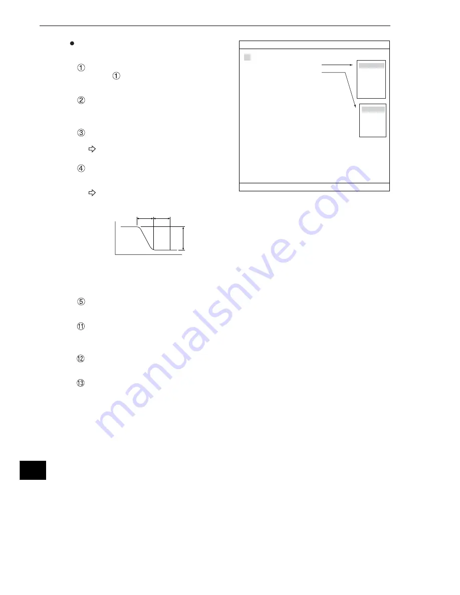
Setting the register conditions for edge
detection
SEARCH AREA
Select "
SEARCH AREA (MDL0)" and press
the SET key to go to the setting screen.
DTECT MODE
Select an image processing method for the
edges.
SEARCH DIR
Specify a search direction.
For details, see page 3-25.
THRESHOLD
Specify a threshold value for binary
conversion.
For details, see page 3-21.
Automatic setting
Select "AUTO-REG" from the upper function menu on the THRESHOLD setting screen. The
controller will set the optimum value automatically.
REF COORD (reference coordinates)
You can change the reference coordinates to any desired position.
SCALE
Enter the actual value of the distance between coordinates 1 and 2. In this example, the distance
is 10 mm. Therefore, enter "10."
SCALE (UNIT)
Select unit of distance between coordinates 1 and 2. In this example, select "mm."
REG (register)
While the cursor is on "EXEC" (execute) press the SET key again. The controller will be
calibrated to treat 1 pixel = 1 mm.
1
SEARCH AREA(MDL0)
SET(224,208)
〜
(287,271)
2
DTECT MODE(MDL0)
CHNG POINT
3
SEARCH DIR(MDL0)
HORIZ(
→
)
4
THRESHOLD(MDL0)
SET(D:050 E:2 F:04)
5
REF COORD(MDL0)
SET KEY(256.240)
6
SEARCH AREA(MDL1)
SET(224,208)
〜
(287,271)
7
DTECT MODE(MDL1)
CHNG POINT
8
SEARCH DIR(MDL1)
HORIZ(
→
)
9
THRESHOLD(MDL1)
SET(D:050 E:2 F:04)
0
REF COORD(MDL1)
SET KEY(256.240)
q
SCALE
000.00
w
SCALE(UNIT)
mm
e
REG
EXEC
1PIXEL
CBP 000.0000 mm
1mm
CBM 000.0000 PIXEL
RED F C1 BRT
CALIBRATION
SCREEN
COND
SAVE DATAIL
SET=WINDOW SET ESC=BACK SEL=CHNG IMG TRG=POPUP
HORIZ
(→)
HORIZ
(←)
VERT
(↓)
VERT
(↑)
CHNG POINT
DRK
→
BRT
BRT
→
DRK
CENT(BRT)
CENT(DRK)
A
Light level
B
Density difference
Edge
width
Flat
width


