Lead Inspection
6-4
6
1
REGISTER NO.
2
DTECT SHAPE
3
SEARCH AREA
4
DTECT MODE
5
SEARCH DIRECT
6
THRESHOLD
COLOR F C1 BRT
SELECT OBJECT TYPE COND
OBJECT TYPE COND
TYPE00
TYPE RUN COND
IMAGE-ADJ
MEA-CND (CAMERA1)
MEAS0
POSI-CORRECT
MEAS01 (INSPECT-LEAD F)
IMG PRE-PROC
MEAS CND
REG-COND
EVALUATION COND
NUM-CALC
OUT-COND
MEAS(NEW)
MEA-CND(CAMERA2)
FINAL NUM. CALC
FINAL OUTPUT COND
OBJ-TYPE I/O
OBJ-TYPE SYS.
SET=TO NEXT SUB-MENU ESC=BACK SEL=CHNG IMG TRG=POPUP
+
+
RECT(ARTIFACT)
LINE
CIRC-L
1
REGISTER NO.
00(0
〜
15)
2
DTECT SHAPE
RECT(ARTIFACT)
3
SEARCH AREA
SET(224,208)
〜
(287,271)
4
DTECT MODE
CENT(BRT)
5
SEARCH DIRECT
HORIZ(
→
)
6
THRESHOLD
SET(D:050 E:2 F:04)
7
EXTENSION
LEAD-LENGTH
8
EXT.MEAS DIRECT
VERTY=+000
RED F C1 BRT
REG COND
SCREEN
COND
SAVE DATAIL
SET=TO NEXT SUB-MENU ESC=BACK SEL=CHNG IMG TRG=POPUP
HORIZ
(→)
HORIZ
(←)
VERT
(↓)
VERT
(↑)
CENT(BRT)
CENT(DRK)
NO
LEAD-LENGTH
BALL-WIDTH
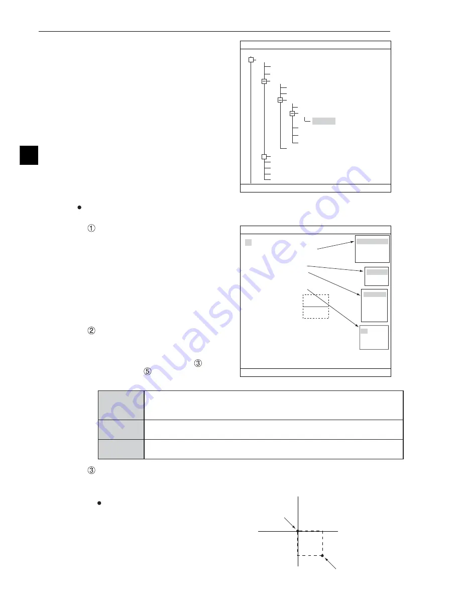
3) On the menu tree, move the cursor to the
"MEAS CND" item, and press the right
arrow key. The sub menu which contains
the "REG COND" item will appear. Move
the cursor to either of these items and press
the SET key.
Set the register conditions
REGISTER NO.
The currently selected register number is
displayed.
If you want to set the measurement
conditions for a different register number,
press the SET key to highlight the register
number currently selected. Then press the
up and down arrow keys to select the
register number whose measurement
conditions you want to set. Press the SET
key to confirm your selection.
DTECT SHAPE
Select a detection shape. Three shapes
are available: "RECT(ARTIFACT)," "LINE,"
and "CIRC-L." Depending on which item is
selected, the choices on lines "
SEARCH
AREA" and "
SEARCH DIRECT" will
change.
SEARCH AREA
Specify a search area. Move the cursor to this line and press the SET key. The currently SET
item will be highlighted. Press the SET key again to enter the setting screen.
When the "RECT (ARTIFACT)" is selected
Specify the upper left and lower right corners
of the rectangular search area.
RECT
(ARTIFACT)
Specify the coordinates of the upper left and lower right corners. The controller
will detect an edge inside this rectangle. For details about processing artifacts,
see page 3-26.
LINE
Specify the coordinates of the starting and end points. The controller will
detect an edge along this straight line.
CIRC-L
Specify the coordinates of the center and radius. The controller will detect an
edge inside this circle.
UP.L
LO.R


