Page 30
Program Mode
This mode is used to set up the
Ultra 5
or change information already set.
You must use either the built-in keypad (standard) or, in the case of the rack
and panel mount, the remote communicator (both keypads are identical in
the way they operate). Alternatively, the unit can be set up with a PC via the
RS 232 Serial Interface.
Entering a value for each of the parameters that are relevant to your
application provides all the programming information.
How to Access Program Mode
Wall and Fascia mount
In the case of the wall and fascia mounted
Ultra 5
, to enter
program mode
,
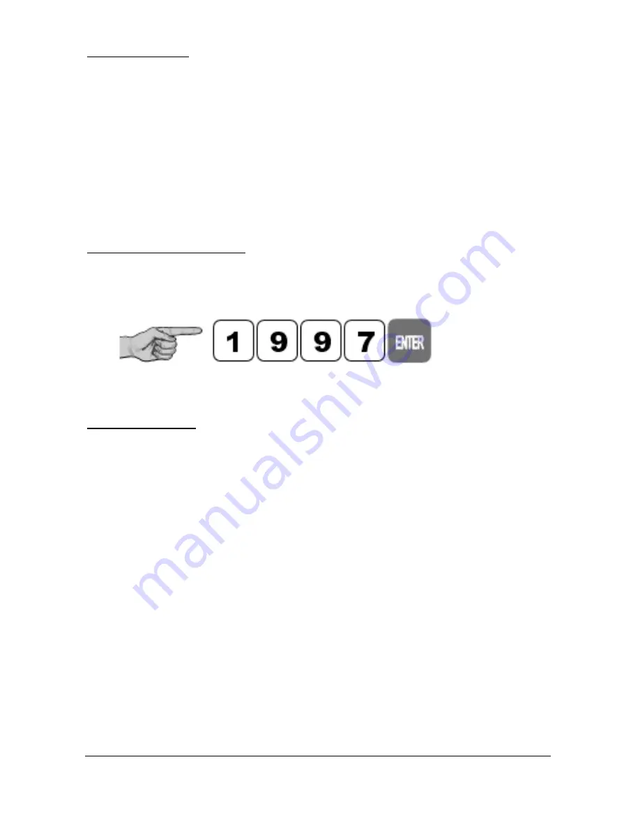
you simply enter the passcode, via the keypad, followed by the
ENTER
key.
The
default passcode
is
1997
, so you would press the following:
Rack and Panel
The Remote Communicator is used to program the rack and panel version of
the
Ultra 5
. Before you can commence programming, it is first necessary to
activate the communication between the
Ultra 5
and the Communicator.
This is achieved by offering the Remote Communicator up to the
Ultra 5
so
that the arrow point in the Pulsar Logo on the Communicator is in line with
the corresponding arrow point on the front panel of the unit and lightly
‘touching’ the unit with the communicator (see following figure).
Confirmation that communication has been successfully achieved will be
indicated by a change of the Communicator status display, at the bottom of
the LCD from “Communicator Off” to “Remote Communicator On”. Once
communications have been activated the Remote Communicator can be used
up to I metre away from the unit but should be ‘aimed’ at the unit whilst
entering information.
On returning the unit to Run Mode ensure that communications between the
Remote Communicator and the
Ultra 5
are switched off by once again
‘touching’ the unit with the Communicator and confirm the display status
changes back to “Communicator Off”
Содержание ULTRA 5
Страница 1: ...ULTRA 5 INSTRUCTION MANUAL ...
Страница 2: ......
Страница 4: ......
Страница 15: ...Page 7 EU Declaration of Conformity Wall Mount ...
Страница 16: ...Page 8 Fascia Mount ...
Страница 17: ...Page 9 Rack and Panel ...
Страница 18: ...Page 10 This page left blank intentionally ...
Страница 21: ...Page 13 The full dimensions of the enclosure are as shown below ...
Страница 23: ...Page 15 The full dimensions of the Fascia mount enclosure are as shown below ...
Страница 25: ...Page 17 Dimensions of the panel enclosure are as shown below VOLTAGE SELECTOR AC POWER FUSE 230 115 ...
Страница 35: ...Page 27 This page left blank intentionally ...
Страница 151: ...Page 143 This page left blank intentionally ...
Страница 240: ...Page 232 This page left blank intentionally ...


